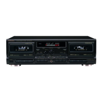
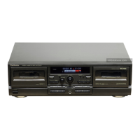
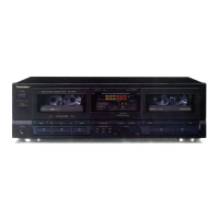
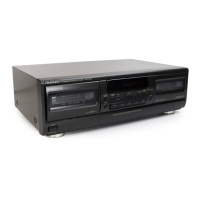
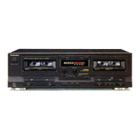
RS・TR575
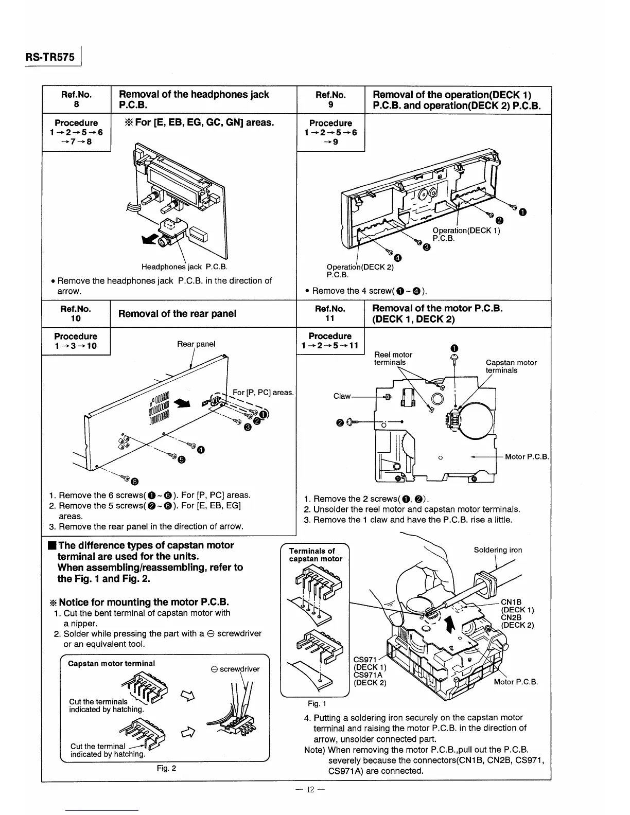
Ref.No.
8
Procedure
1→2→5→6
→7→8
Removal of the headphones lack
P.C.B.
※For【E,EB,EG,GC,GN】areas.
Headphoneslack P,C.B。
●Remove the headphones jack P,C.B、in the direction of
arrOW.
Ref.No.
10
Procedure
1→・3→10
Removal of the rear panel
Rear panel
麟 監、
一、⑤④
・ For IP,PC】areas.
、、
・轡
③
『、⑥
1.Removethe6screws(①一⑥)。For【P,PClareas.
2.Removethe5screws(②〜⑥).For[E,EB,EG】
areas,
3.Remove the rear panel in the direction of arrow,
Ref.No.
9
Procedure
1→2→5→6
→9
Removal ofthe operation(DECK1)
P.C.B.and operation(DECK2)P.C.B.
Operation(DECK2)
P.C,B.
④
θ1
コ・廻1
!
γ ①
vイ ②
Operation(DECK1)
P.C.B.
③
・Removethe4screw(①〜④).
Ref.No.
11
Procedure
1→2→5→11
Removal ofthe motor P.C.B.
(DECK1,DECK2)
Reel motor
terminaIS
①
Claw
②
づ一→
Capstan motor
te,rminaIS
4 1
◎1
8
O
l l
Motor P.C.B.
1,Removethe2screws(①,②).
2.Unsolder the reel motor and capstan motor terminals.
3.Remove the l claw and have the P.C.B.rise a Iittle.
■The difference types of capstan motor
terminal are used forthe units.
When assemblinglreassembling,referto
the Fig.1and Fig.2.
※Notice for mounting the motor P、C.B.
1.Cut the bent terminal of capstan motor with
anipper.
2.Solder while pressing the part with a e screwdriver
Or an eqUiValent tOOL
Capstanmotortermina1
㎝tt㎏㎞m陥命母
indicated by hatching、
㏄tt㎏㎞mh禽
indicated by hatching。
ゆ
e screwdriver
Fig。2
Te『minals of.
capstan motor
CS971
(DECK1)
CS971A
(DECK2)
Soldering iron
4 CNIB
イ 、 ¥》 (DECK1)
轡詠甥騰2)
一ll蜥 。z
N 電
$旨
Motor P,C,B.
Fig.1
4.Putting a soidering iron securely on the capstan motor
terminal and raising the motor P,C,B、in the direction of
arrow,unsolder connected pa口:,
Note)When removing the motor P.C.B.,pull outthe P℃B。
severely because the connectors(CNI B,CN2B,CS971,
CS971A)are connected.
一12一