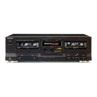
RS・TR575
o
◎
Step4
Step5
▼
A
甥瀟贈編2昌鯉銚壽翁差N↓
The counter shows a four・digit hex number。 The two high・order diglts
indicate a ROM address,and the two low・order digits indicate the data
stored at that address.
●Load a Normal blank test tape(QZZCRA)into the deck under test.
Press the ATC button,then the REC button. The display wiII flash皿
sIowly.(At this point the deck automaticay adjusts the overall gain
and frequency response.)
●Afterthe above setting,theoverall gain forselection of CrO2and MetaI
tape wibe automatically set by the ROM and stored in the ROM,
Noセe=lf adjustment of OVERALL GAIN or OVERALL FREQUENCY
RESPONSE fails,the display wi刊ash皿rapidly.
After a successful adjustment,the display wino longer show
皿.
「
「
一 一
』一
しし
一 一
鷲 Y
Example=SetFFin address O3
(see Fig・3)・ Step9
』 r 一
『ン
仁コ コ〔
9W
h
The
is
とSetthesedigitsuSingtheFF。r
,
REW button.
hlgh−and Iow−order digits
of the address increment alter−
nately each time the FF button
pressed.The REW button
causesthesedigitstodecrement
altemately.
For fast incrementing or decre−
menting,hold down the FF or
REW button.
﹀ ム
一Set these digits using the FWD、
PLAYorREV.PLAYbutton. The
high・and Iow・order digits of the
data increment altemately each
time the FWD.PLAY button is
pressed. TheREV.PLAYbutton
causes these digits to decrement
alternately. For fast incre一
↓
モsetthesedigitst.
5Ausing the FWD.
PLAY or REV.PALY
button.
Set these digits to03
using the FF or REW Step10
button.
Note=
of the
●
Removetheshorting clip from theTest Modeterminals. The FLdisplay
will stop blinking.
menting or decrementing,hold
down the FWD.PLAY or REV、
PLAY button.
*The data writing process is
complete when the next
add「essnumbe「apPea「s・ 旧hemicr・pr・cess・risreplaced,itisn・tnecessaryt・replace(・rwri量
For example,writing
data O3.5A has been
completed when the EEPROM MAP
「
「
Begin from address OO and write data up to address7F(data in
口).Checkthatthedataataddress7Fis00(end),andthenexit
the write mode.
「
F
address O4is displayed、
0
1
2 3 4 5
6
7
0
00
一
一
一 一 一
一 一
Blinks
1
一
一
一
一
一 一
一 一
2
一 一
一 一 一 一
一 一
廟 畠 隔 一
一一騨一7
1 __.L_
一 一 ● 一 嶺
!一一一。一。一一。一〇一一一。一一D鱒噸。一一一、
団 巌。一15鱒沿}6−3。ロ。+2+4 1〉
l R l
\.一一。。一_。。顧一__一一一,一一。一一一。一。
3
5A
一
一 一
一
一
一
一
4
一 一
68
84
90
68
84
90
5
一 一
78 60
60
78
60 60
6
}
一
38
30
18
38 30
18
PIAYBACK GAlN ▼
7
一
一
64 68
78
64 68
78
●Set the AF osciators output frequency to315Hz1−20dB(100mV)
(see Fig.2).
●With no tape Ioaded in the deck,press and hoId the REC button、
Adjust the test signal Ievel using the Rec.Level and Balance controls
until the Iine output levels on both channels are320mV。When the
adlustment is complete,release the REC button.(The deck stores
the data at the moment the REC button is reIeased.)
●Load the test tape,QZZCFM,into the deck and Iocate the section of
the tape where the playback gain test tone(315Hz,OdB)is recorded,
then playback the portion. Press the ATC button,and the display wi
flash皿sbwly,meaning that playback gain is belng automaticay
adjusted. Press the pIay button.(At this point the deck automaticaIly
adjusts playback gains.) After this play back the tape and verify that
the output level fas in the specified range.
8
一 一
A8
BO
8C
A8
BO
8C
9
一 一
9A
AA
94
50 70 68
A
一
一
6A
OF
一
80 80 80
B
一 一
70
2B
一
40
50
AO
C
一 一
50
12
一
B8 B4
B8
D
一
一
72
07
一
66
5E
40
E
一
一
4C FB
00
70
74 02
F
一
一
55
F5
00
47 47
00
Fig、3
Note=At an address with no data value indicated(e.g.01→一),the ROM operates
normally irrespective of the kind of the data supplied、
Standard value=320mV±0.5dB
UN〔OUτ ^
No量e=1f adlustment of PLAYBACK GAIN fails,the display w1刊ash皿
rapidly. Afterasuccessful adjustment,thedisplaywilI no Ionger
show皿.
1尉E旧
﹇団.凝
◎
、\ /
o客}二二一盤5二二−=
=二:ユ
し甲喚
v v
AF
) V
∈VM
050量固or
Fig.2
▼
Example=SetFFin address O3
(see Fig.3).
︳
コ コ〔
モsetthesedigitst.
5Ausing the FWD.
PLAY or REV.PALY
button.
Set these digits to03
using the FF or REW
button.
INITIAl SETTING UP FOR OVERALl GAIN
AND OVERAIL FREOUENCY RESPONSE
Step9
●Load a Normal blank test tape(QZZCRA)into the deck under test.
Press the ATC button,then the REC button. The display wiII flash皿
sIowly.(At this point the deck automaticay adjusts the overall gain
and frequency response.)
●Afterthe above setting,theoverall gain forselection of CrO2and MetaI
tape wibe automatically set by the ROM and stored in the ROM,
Noセe=lf adjustment of OVERALL GAIN or OVERALL FREQUENCY
RESPONSE fails,the display wi刊ash皿rapidly.
After a successful adjustment,the display wino longer show
皿.
Step10
Removetheshorting clip from theTest Modeterminals.
will stop blinking.
The FLdisplay
Step6
Step7
Step8
*The data writing process is
complete when the next
address number appears.
For example,writing of the
data O3.5A has been
completed when the
address O4is displayed、
AFo50a竃or
UN〔OUτ
Fig.2
∈VM
Note=睡the microprocessor is replaced,it is not necessaryto replace(orwri量e data to》the EEPROM.
●EEPROM MAP
Fig、3
Note=At an address with no data value indicated(e.g.01→一),the ROM operates
normally irrespective of the kind of the data supplied、
◎
一23一
一24一