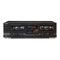
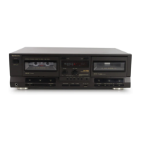
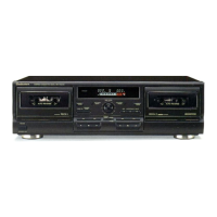
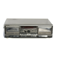
RS・TR575
■WRITING TO EEPROM
This unit is equipped with EEPROM memory that stores a variety of design data and performance data
such as playback galn,bias value,recording gain,recording equalization,etc.,which was programmed
at the factory.
This EEPROM memory is capable of being read and written to more than100,000times. To iustrate
this,if one ATC operation is performed every hour continuously every day for ten years,it worId stlII be
possible to successfuy read and write with the EEPROM.
Data is actuay written in this EEPROM onIy when ATC ls actuated or when power supply is tumed on or off.
Since it hardly breaks down,there wiII scarcely occur such a trouble as to require repIacement.
Measurement Condi量ion
●Recording・level control;Maximum
●Recording・balance controll Center
●Reverse−mode selector switchl#
●Tape・to−tape recording−speed switchl Off
●Dolby NR switchl Off
●ATC switchl Off
●Make sure heads are clean
●Makesurecapstan and pressure rollerareclean
●Judgeable room temperature20±5。C(68±9。F)
Measu『ing ins量『ument
●EVM(Electronic Voltmeter) ●ATT(Attenuator)
●Osc眺書oscoρe ●Reslstor(600Ω)
●AF osciator
NOTE=Before adjustment,be sure to set the AF osciIlator output IeveI to OdB(1kHz):1V
Test量ape
●Playback gain adjustment(315Hz,OdB)l QZZCFM
●OveraII gain adjustment and Overafrequency response
Normal reference blank tape;QZZCRA
CrO2reference blank tape l QZZCRX
Metal reference blank tape;QZZCRZ
NOTE=Step2tostep70nlyhasto bedoneafterexchangeofthe EEPROM.
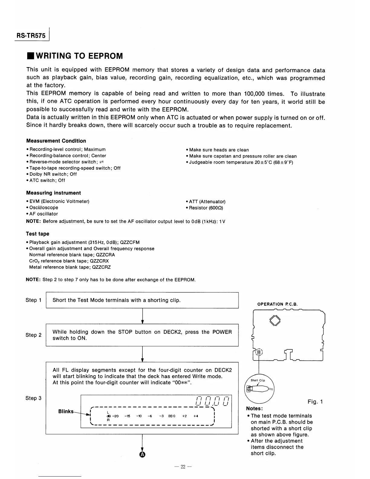
Step1
Step2
Step3
Short the
Test Mode terminals with
ashorting clip.
「
F
WhiIe holding down the STOP button on
DECK2,press the POWER
switch to
ON.
↓
AII
FL display segments except for
the four・digit counter on DECK2
will start bIinking to indicate that the
deck has entered Write mode.
Atthis point
the four薗digit counter
wiIl indicate00**.
一 一 一 _
ノ
Blinks
8 L
、、酒 の{。.15欄
l R
,H,
一騨一_一,爾一,一一瞬剛騨r隅_.一嗣障鋼一層 周一欄一一;「_ 一 。一 『
〆一噸噸 一、
1
−6 −3 ロCO +2 +4 1
碧
\墜_一一_一一一一_一,一一一_____一_一___.ノ
o
OPERATION RC。B,
贋〉
◇
Fig.1
Notes:
●The test mode terminals
on main P.C.B.should be
shorted with a short clip
as shown above figure.
●After the adjustment
itemS diSconnect the
short c聴p.
一22一