I SL-1200M3D
• Schematic Diagram
Notes: ,S201
,$202
.S203
,S301
*$302
,S401
,S601
.VR201
: SPEED SELECTOR (33 rpm) switch.
: SPEED SELECTOR (45 rpm) switch.
: START/STOP switch.
: PITCH CONTROL RESET switch in "OFF" position. (Interlocked with VR303)
: PITCH RESET switch in "OFF" position.
: STYLUS ILLUMINATOR switch in "ON" position.
: POWER switch in "ON" position.
: BRAKE ADJUSTMENT VR.
•VR301 : PITCH CONTROL + 0% ADJUSTMENT VR.
,VR302 : PITCH CONTROL GAIN ADJUSTMENT VR.
•VR303 : PITCH CONTROL ADJUSTMENT VR. (Interlocked wwith $301)
• The voffage value and waveforms are the reference voltage of this measured by DC electronic voltmeter (high impedance)
and oscilloscope on the basis of chasssis.
Accordingly, there may arise some errors in the voltage values and waveforms depending upon the internal impedance of the
tester or the measuring unit.
• important safety notice:
Components identified by ,_ mark have special characteristics important for safety. When replacing any of these components,
use only manufacture's specified parts.
NO MARK: Voltage when at a stop
) : Voltage during rotation
: +B Line
For U.S.A. model only]
CAUTION: FORCONTINUEDPROTECTION
AGAINSTFIREHAZARD,REPLACEONLYWITH
SAM_TYPE FI 1.2A125V FUSE.
RISK OF FIRE-REPLACE FUSE AS MARKED,
[For CANADA model only]
FUSE CAUTION
These symbols located near the fuse
indicates thai the fuse used is a fast operating
type, For continued protection against fire
harzard, replace with the same _ fuse. For fuse
rating, refer to the marking adjacent to the
symbol.
Cesymbole indiquaquale luslble utilisd
est _1 rapide. Pour une protection parrrmnente,
n' utiliser qua des fusibles do m_me type. Co
dernier est indiqud t_ q0 le pr6sent eymbola
est appos6.
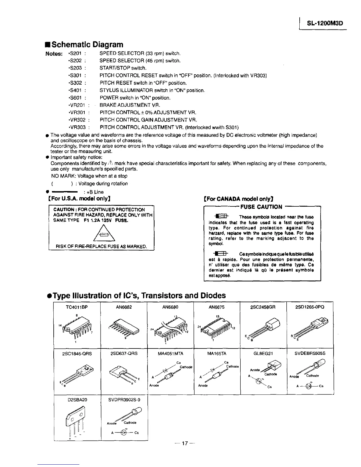
• Type Illustration of IC's, Transistors and Diodes
TC4011BP
8
1
2SC1846-QRS
D2SBA20
AN6682
9
2SD637-QRS
C
SVDPR3902S-9
A@Ca
AN6680
24_ 2
MA4051 MTA
Ca
A _ cath_
AN6675
t3
24_ 12
1
MA165TA
ca
A _ath_
Anode
2SC2458GR
GL8EG21
An °de
CalhOde
A_C a
2SD1265-0PQ
SVDEBR5505S
A@Ca
+
--17--
 Loading...