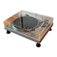
l SL-1200M3D
• Measurements and Adjustments
Notes: • Make the following adjustmentsafter replacing parts suchas IC's, Transistors,Diodes, etc.
• Condition of the set.
1.Power switch........................ ON
2 Pitchcontrol......................... Center position
3.Speed selector switch............. 33 r.p.m.
• Instrumentsto be used
1Tester
2.Frequency counter
Parts
Adjustment Connection adjusted Procedure
Frequency counter 1. Connect the frequency counter and turn the power supply ON.
Pitch control ± 0% VR301 2. Set the pitch controt knob to "0",
I (+} ... TP27
adjustment (-) ... Earth point (Fig. 1) (Indicator lights up.)
3.Adjust VR301 so that the frequency is 262.08 kHz ± 0.05 kHz.
1. Set the pitch control knob to "0".
Tester 2, Pull out the connectorCN 102 of drive P.C.B.
2 Pitch control gain (+} ... CN102 terminal _) VR302 3. Connect the testerto terminals,(_ and (_) of connector CN102
adjustment (-) ... CN102 terminal _) (Fig. 2) on the pitch control P.C.B. side.
4, Adjust VR302 sothat the resistance value of the tester is
2,875 ± 0.25 kQ.
VR201 1.Adjust VR201 so that the rotation at 33 r.p.m, stops within
3 Brake adjustment
(Fig. 1) the angle of 30° - 210 ° after depressing the stop position.
• Alignment Points
Please refer to PrintedCircuit Board Diagram for test point locations.
pITCH CONTROl.
-t- 0% ADJUSTMENT
BRAKE
ADJUSTMENT
PITCH CONTROL
P.C.B.
oa_o
0
YEL
=5
=6
=7
= 13
PITCHCONTROL
GAIN ADJIJSTMENT
Fig. 2
DRIVE P,C B
Fig. 1
-- 23
 Loading...