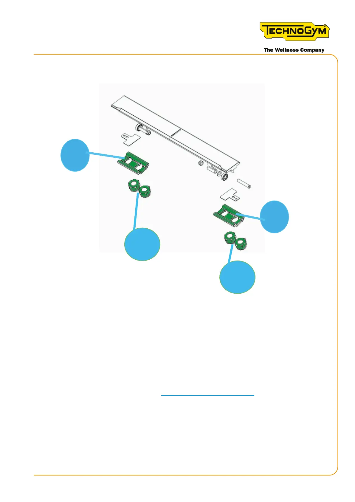
Tighten one of the two self-locking nuts with a tightening torque of 2 Nm (1.5 lbf-ft). Tighten the
second self-locking nut with a tightening torque of 1.6 Nm (1.2 lbf-ft).
2
3
3
2
Figure 59
7.10 DISASSEMBLING THE FRONT ROLLER
Follow all the steps to:
• Disassemble the front right guard and the front left guard.
• Remove the front right pulley.
Remove 4 slats as explained in paragraph “7.9.1 Disassembling the slats”.
1. Loosen the grub screws locking the ange on both the right and left sides of the shaft.
2. Loosen the grub screws locking the front pulley on both the right and left sides of the shaft.
3. Remove the nuts locking the right bearing in place. Remove the screws. Remove the ange.
4. Remove all the snap rings from their seats to enable the shaft to move on its axis from right
to left. Hit with the rubber mallet.
Skillmill:
Technical Service Guide - Rev. 3.5
Page 107email: support@technogym.com