© Technosoft 2011 13
IDMx40 Technical Reference
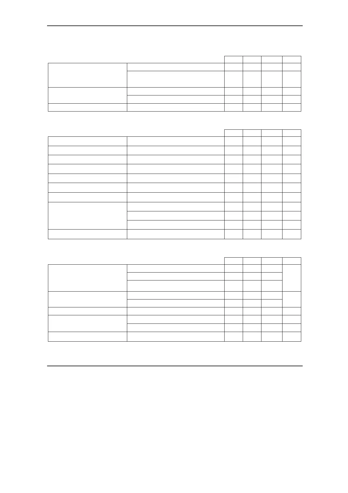
CAN-Bus Supply Input (isolated)
Measured between CAN_V+ and CAN_GND.
Min. Typ. Max. Units
Nominal values 8 24 30 V
DC
Supply voltage
Absolute maximum values, surge
(duration ≤ 10ms)
†
-0.5 32 V
CAN-Bus idle 12 25 mA
Supply current
CAN-Bus operating at 1Mbit/s 60 180 mA
Isolation voltage rating Between CAN_GND and drive GND 200 V
RMS
Motor Outputs
All voltages referenced to GND.
Min. Typ. Max. Units
Motor output current IDM240-5EI Continuous operation -5 +5 A
RMS
Motor output current IDM640-8EI Continuous operation -8 +8 A
RMS
Motor output current, peak -16.5 +16.5 A
Short-circuit protection threshold
±20 ±22 ±24
A
Short-circuit protection delay 10 20 40
μS
On-state voltage drop
Output current = ±8 A
-900
±200
+350 mV
Off-state leakage current -1
±0.1
+1 mA
F
PWM
= 20 kHz, +V
MOT
= 12 V 50
μH
F
PWM
= 20 kHz, +V
MOT
= 48 V 200
μH
Motor inductance
F
PWM
= 20 kHz, +V
MOT
= 80 V (IDM640-8EI) 400
μH
ESD Protection Human Body Model
±25 ±25
kV
24 V Digital Inputs (opto-isolated)
All voltages referenced to 0V
PLC
.
Min. Typ. Max. Units
Logic “LOW” -5 0 1.2
Logic “HIGH” 8 24 30
Input voltage
Absolute maximum, surge (duration ≤ 1s)
†
-30 +80
V
Logic “HIGH” 2.5 10 15
Input current
Logic “LOW” 0 0.2
mA
Input frequency 0 5 kHz
Pulse “LOW”-”HIGH”-“LOW” 10
μs
Minimum pulse width
Pulse “HIGH”-“LOW”-”HIGH” 100
μs
ESD Protection Human Body Model
±8 ±10
kV