© Technosoft 2011 45
IDMx40 Technical Reference
3.2.5.1 Recommendations for Analogue Signals Wiring
a) If the analogue signal source is single-ended, use a 2-wire shielded cable as follows: 1
st
wire
connects the live signal to the drive positive input (+); 2
nd
wire connects the signal ground to
the drive negative input(-).
b) If the analogue signal source is differential and the signal source ground is isolated from the
drive GND, use a 3-wire shielded cable as follows: 1
st
wire connects the signal plus to the
drive positive input (+); 2
nd
wire connects the signal minus to the drive negative input (-) and
3
rd
wire connects the source ground to the drive GND
c) If the analogue signal source is differential and the signal source ground is common with the
drive GND, use a 2-wire shielded cable as follows: 1
st
wire connects the signal plus to the
drive positive input (+); 2
nd
wire connects the signal minus to the drive negative input (-)
d) For all of the above cases, connect the cable shield to the drive I/O connector frame and
leave the other shield end unconnected to the signal source. To further increase the noise
protection, use a double shielded cable with inner shield connected to drive GND and outer
shield connected to the drive I/O connector frame. Leave both shields unconnected on the
signal source side
e) If the signal source output voltage is larger than +/-10V, use a 3-resistor differential divider,
located near the IDMx40 I/O connector. Choose the divider resistances as low as possible,
close to the signal source output current limit, to minimize the noise
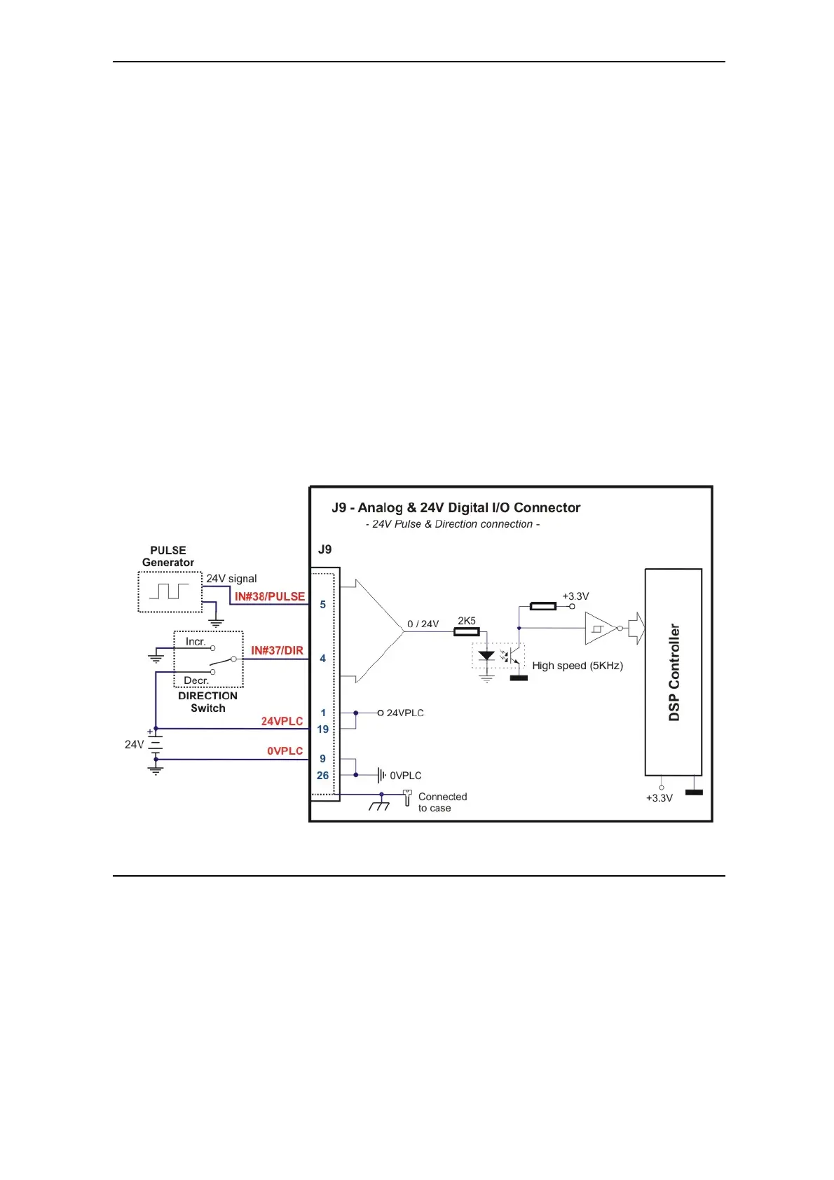
Figure 3.25 J9 – 24 V Pulse & Direction connection
IDMx40