36 / 52
After every welding operation, the display shows the following information:
$ The welding program used.
$ The number of the welding spots carried out as of the last counter reset.
$ The current conduction angle of the last welding spot.
$ The set welding time.
$ The value of the current of the last welding spot.
READING OF THE WELDING CURRENT AND THE CONDUCTION ANGLE
The value of the current, which the control unit measures and which is displayed, stands for the
average of the RMS values measured for every welding time half-period. The displayed value always
refers to the main adjustment i.e. to that of the WELD 1 parameter. For pulse welding spots the value
of the current will always be the average value of all the impulses.
The control unit also measures the welding current conduction angle. The conduction angle stands for
the time in which the current was carried during the half-period. The displayed value stands for the
average of the values measured for each welding time half-period.
The displayed value always refers to the main adjustment i.e. to that of the WELD 1 parameter. The
conduction angle of the current that circulated during the slope times is never measured. For pulse
welding spots the value of the angle is related to the last impulse the maximum value of which can be
180 degrees.
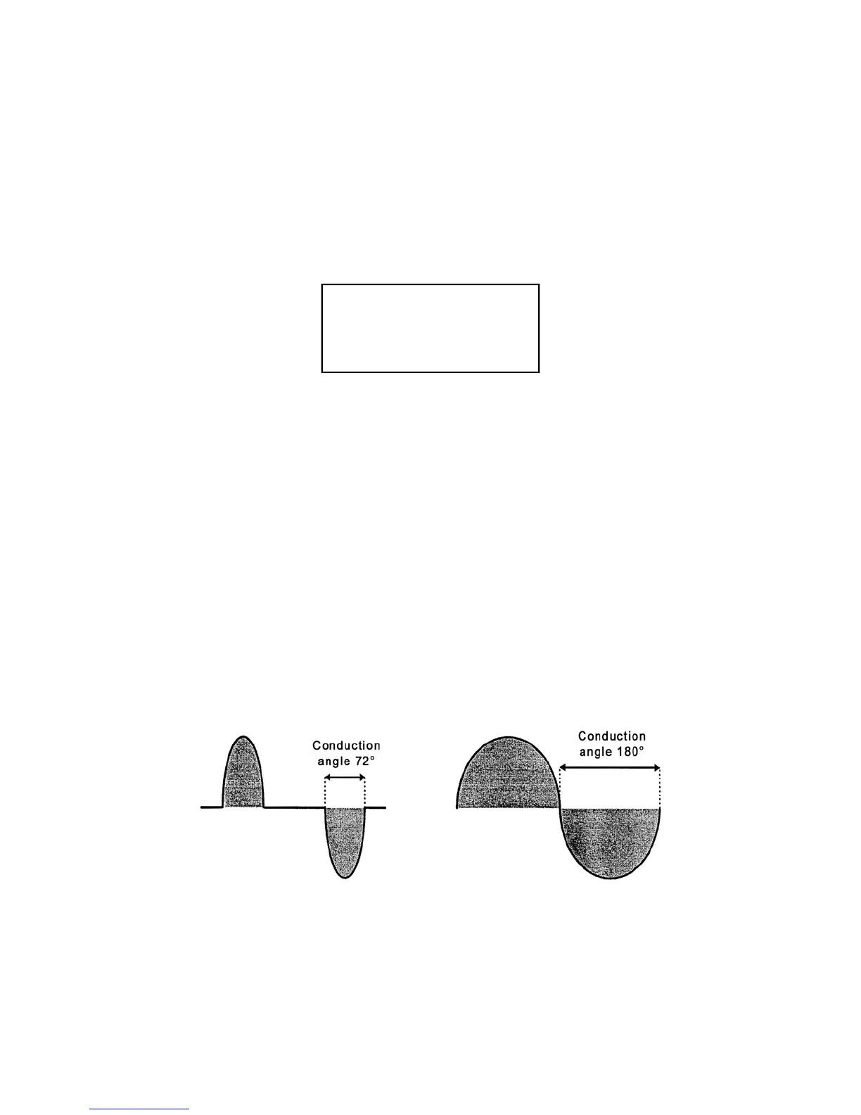
Example of currents with different conduction angles:
PROG. 01 SPOT 12340
WELD CYCLE 01.0
CURRENT RMS 43.26
CONDUCTION DEG 142°
If a test welding stop is performed in "NO WELD" mode, the current and conduction angle values
displayed will be zero.