41
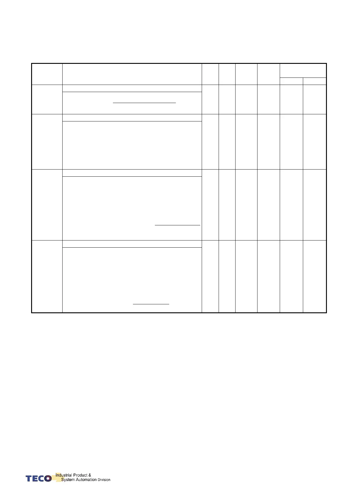
OFF-Line adjustment will change the parameters as follows:
Parameter Name
Defa
ult
Unit
Setting
Range
Control
Mode
Communication
Adress
RS232 RS485
Cn025
Load-Inertia ratio
10 x0.1
0
│
1000
Pi
Pe
S
5FBH 0019H
%100
)
M
Inertia(JMotorRotor
)
L
(J
aToMotorLoadInerti
aRatioLoadInerti
Sn211
Speed loop Gain 1
40 Hz
10
│
1500
Pi
Pe
S
530H 020BH
Speed loop gain has a direct effect on the frequency
response bandwidth of the Speed-control loop.
Without causing vibration or noise Speed-loop-gain
can be increased to obtain a faster speed response.
If Cn025 (load Inertia ratio) is set correctly, the
speed-loop-bandwidth will equal to speed-loop-gain.
Sn212
Speed-loop Integral time 1
100
x0.2
ms
1
│
5000
Pi
Pe
S
531H 020CH
Speed loop integral element can eliminate the steady
speed error
and react to even slight speed variations.
Decreasing Integral time can improve system rigidity.
The formula below shows the relationship between
Integral time and Speed loop Gain.
ainSpeedLoopG
tTimeConsntegrationSpeedLoopI
2
1
5tan
Pn310
Position Loop Gain 1
40 1/s
1
│
1000
Pi
Pe
55AH 030AH
Without causing vibration or noise on the mechanical
system the position loop gain value can be
increased to speed up response and shorten the
positioning time.
Generally, the position loop bandwidth should not be
higher then speed loop bandwidth. The relationship
is according to the formula below:
5
2
ainSpeedLoopG
opGainPositionLo
 Loading...

