80
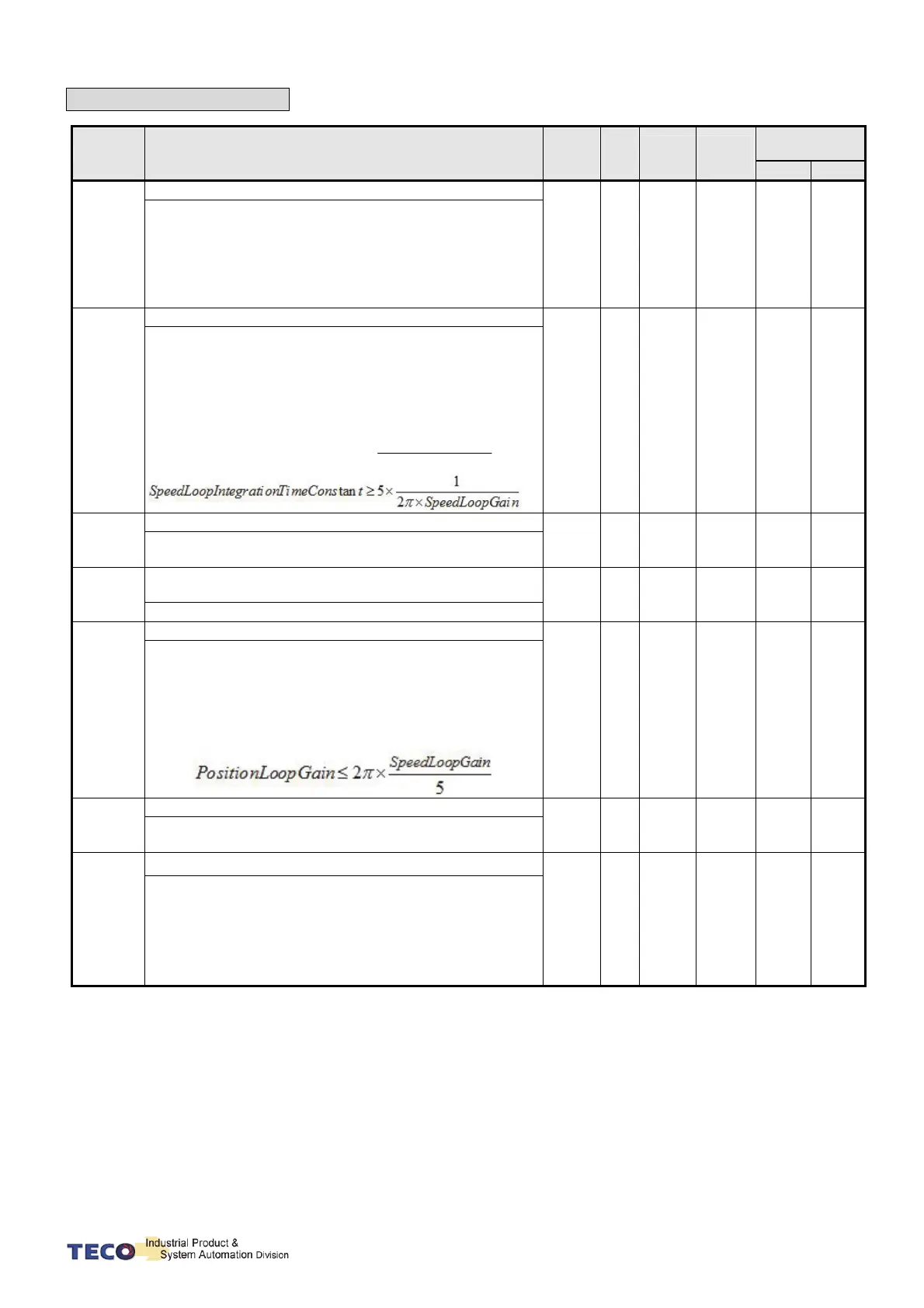
Quick Set-up Parameters
Parameter
Name & Function Default Unit
Setting
Range
Control
Mode
Communication
Address
RS232 RS485
◆
qn501
Speed Loop Gain 1.
( Same function as Sn211)
40 Hz
10
│
1500
Pi
Pe
S
530H 0401H
Speed loop gain has a direct effect on the frequency
response bandwidth of the Speed-control loop.
Without causing vibration or noise Speed-loop-gain can
be increased to obtain a faster speed response.
If Cn025 (load Inertia ratio) is correctly set, the
speed-loop-bandwidth will equal to speed-loop-gain.
◆
qn502
Speed-loop Integral time 1.
(Same function as Sn212)
100
x0.2
ms
1
│
5000
Pi
Pe
S
531H 0402H
Speed loop integral element can eliminate the steady
speed error
and react to even slight speed variations.
Decreasing Integral time can improve system rigidity.
The formula below shows the relationship between
Integral time and Speed loop Gain.
ainSpeedLoopG
tTimeConsntegrationSpeedLoopI
2
1
5tan
◆
qn503
Speed Loop Gain 2.
(Same function as Sn213)
40 Hz
10
│
1500
Pi
Pe
S
53AH 0403H
Refer to qn401
◆
qn504
Speed Loop Integration Time Constant 2.
(Same function as Sn214)
100
x0.2
ms
1
│
5000
Pi
Pe
S
53BH 0404H
Refer to qn402
◆
qn505
Position Loop Gain 1. (
Same function as Pn310)
40 rad/s
1
│
1000
Pi
Pe
55AH 0405H
Without causing vibration or noise on the mechanical
system the position loop gain value can be increased to
speed up response and shorten the positioning time.
Generally, the position loop bandwidth should not be
higher then speed loop bandwidth. The relationship is
according to the formula below:
◆
qn506
Position Loop Gain 2 (
Same function as Pn311)
40 rad/s
1
│
1000
Pi
Pe
551H 0406H
Please refer to qn405
◆
qn507
Position Loop Feed Forward Gain
0 %
0
│
100
Pi
Pe
55BH 0407H
It can be used to reduce the follow up error of position
control and speed up the response.
If the feed forward gain is too large, it might cause speed
Overshoot and in position oscillations which result in
the repeated ON/OFF operation of the output contact
INP(“In Position” output signal).

 Loading...
