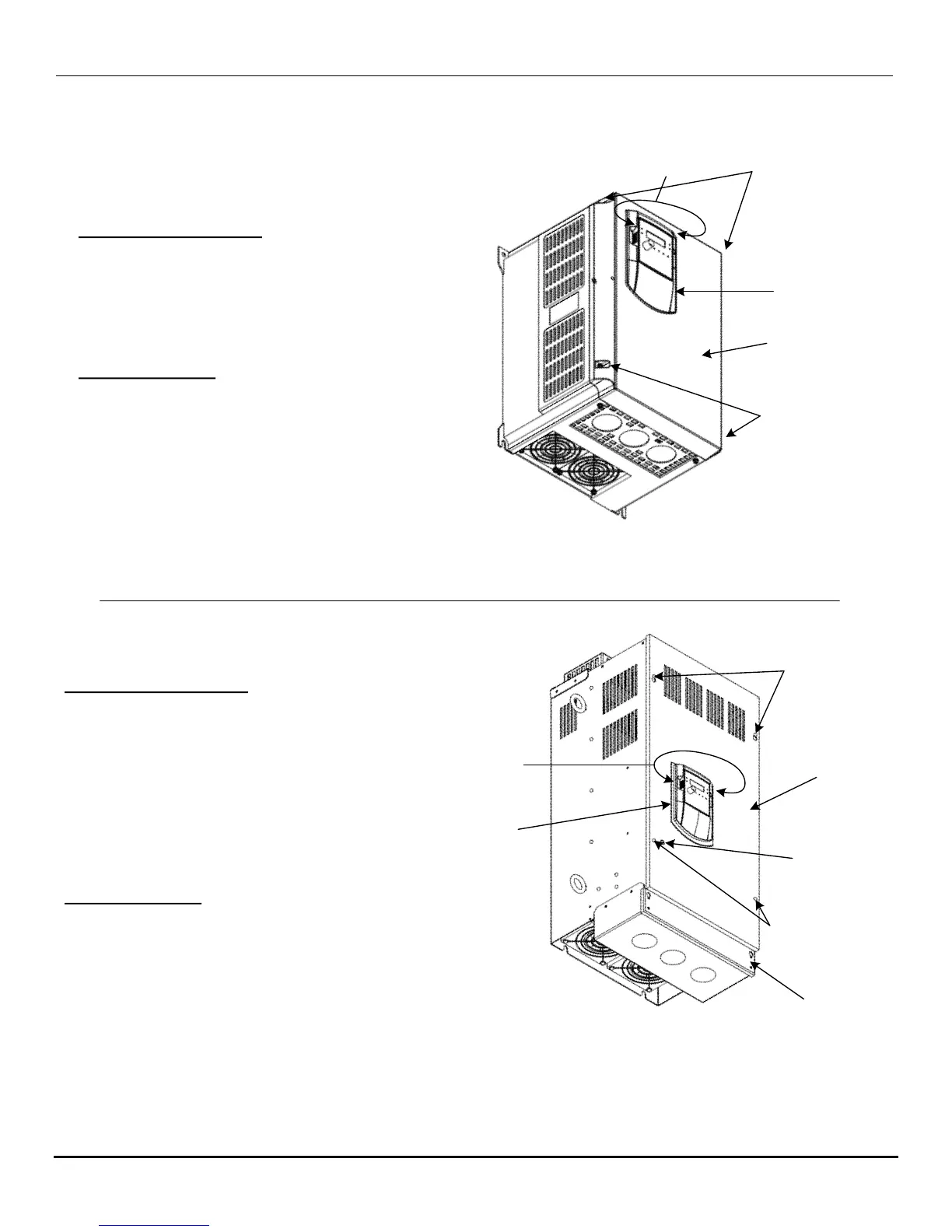
Main
Cover
Digital
Operator
Conduit
Box
Cover
“A”
Mounting
Screws
(2)
“B”
Mounting
Screws
(2)
Charge
Indicating
Lamp
Finger
Removal
Grips
(Both
sides)
Cover Removal Procedure
1 – First remove the Digital Operator by gripping at
the points shown and pulling straight out. (The
Operator has a connector that plugs directly into
to the chassis.)
2 – Loosen both mounting screws “A” and back
out but do not remove.
3 – Loosen and remove both mounting screws “B”.
4 – Slide the main cover up and lift off.
5 – The conduit box cover if needed may be
removed in essentially the same way.
Cover Replacement
1 – Slide the main cover screw slots over screws “A”
and set in place.
2 – Insert and tighten screws “B” and then tighten
screws “A”.
3 – Next insert the Digital Operator by carefully lining
up the connector and pushing straight in.
4 – Replace the conduit box cover if it was removed.
Fig. AD.4 Cover Removal for N3 Frame Sizes 5 & 6
Cover
Digital
Operator
Mounting
Screws
Finger Removal
Grips
(Both sides)
Cover Removal Procedure
1 – First remove the Digital Operator by gripping at
the points shown and pulling straight out. (The
Operator has a connector that plugs directly into
to the chassis.)
2 – Loosen the four mounting screws and lift off the
cover.
Cover Replacement
1 – Set the cover in place and secure with the four
mounting screws.
2 – Next insert the Digital Operator by carefully lining
up the connector and pushing straight in.
Mounting
Screws
(4)
Fig. AD.3 Cover Removal for N3 Frame Size 4

 Loading...


