N3 Drive Operations Manual
Inverter Wiring; Input Power Wiring 12
8.3 Motor Cable Length
The length of the cables between the motor and inverter can cause a significant phase to phase voltage
reduction at the motor due to the voltage drop across the cables. To calculate this reduction, apply the following
formula:
Phase-to-phase voltage drop (V) = 3 ×resistance of wire (Ω/km) × length of line m) × current×10
-3
.
(km=3280 x feet) (m=3.28 x feet )
8.4 Cable Length vs Carrier Frequency
The allowable setting of the PWM carrier frequency is also determined by motor cable length and on is specified
in the following table.
Table 8.2 Cable Length vs Carrier Frequency
Cable length between the
inverter and motor
ft / m
Recommended carrier
frequency allowed
Setting of parameter
A044
8.5 Inverter Grounding
The proper grounding scheme for one or more inverters is very important to ensure personnel safety as well as
equipment performance. The following will discuss the proper grounding procedures.
The grounding resistance for the 230V class; <100, the 460V class; <10.
The ground wire size (AWG) is per electrical code.
Do Not share a ground with any other equipment with high current loads such as welding machines, presses,
etc. Connect the inverter to its own dedicated ground.
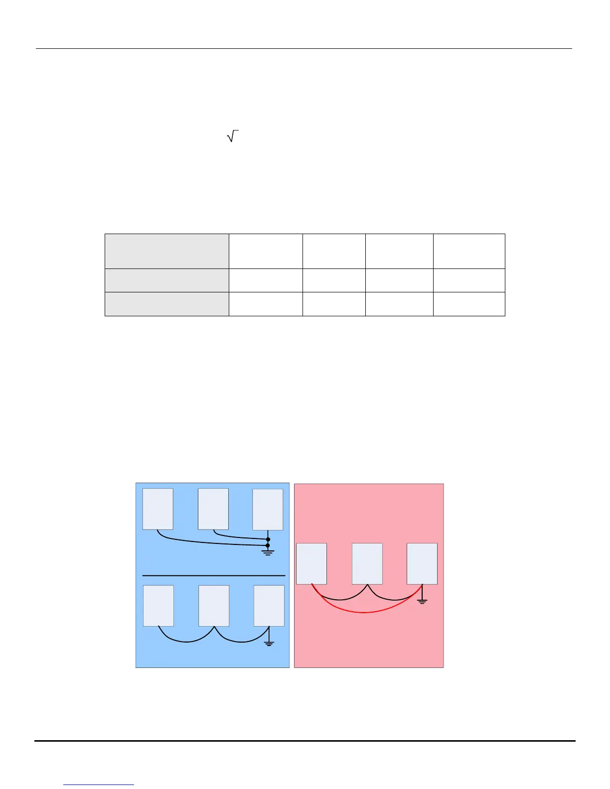
Do Not make a loop when several inverters share a common ground point (See Fig. 8.5c).
N3 N3
N3
N3 N3 N3
a) Correct
b) Correct
N3 N3 N3
c) Incorrect
Loop
Fig. 8.5 Inverter Grounding

 Loading...


