N3 Drive Operations Manual
Keypad Functions & Navigation; Key Functions 23
17.0 Keypad Key Functions and Navigation
The N3 keypad, provides all the necessary functions to allow full control of the N3 inverter. The keypad has
membrane type keys and a 7 - segment 4 - digit LED display. Also located on the keypad is a potentiometer that can
be used to control inverter output frequency when selected as the control source. A remote keypad is available as an
option, and is covered more in detail in the Option Modules Sec. 20.0.
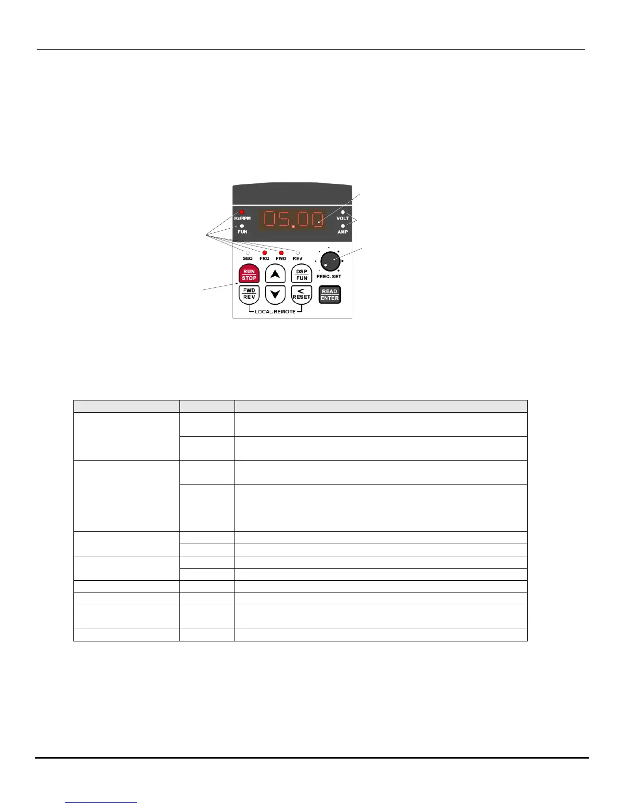
17.1 N3 Keypad
Output frequency
control potentiometer
(when selected)
4 digit 7 segment
LED display
Membrane keys
LED indicators
LED indicators
Fig. 17.1 N3 Keypad
17.2 Keypad LED Functions
Table 17.1
Run Command Source is from the keypad (b000=0000)
(factory default)
Run Command Source is from external terminal (b000=0001),
or RS485 communication control (b000=2)
Frequency Command Source is from the keypad
(b004=0000) (factory default)
Frequency Command Source is from potentiometer on
keypad (b004=1), external analog signal (b004=0002), up /
down frequency control using MFIT (S1-S6) (b004=0003) or
RS485 communication control (b004=0004)
Drive is running in the forward direction
Drive is in the stop mode
Drive is running in the reverse direction
Drive is in the stop mode
Entering A or b parameters
Display is showing output frequency
Display is showing motor voltage (b014=0001), DC bus
voltage (B015=0001) or PID feedback voltage (b016=0001)
Display is showing motor current (b013=0001)
*Note – On initial powerup (factory default), the only LEDs that are on are Hz/RPM and FWD.

 Loading...


