N3 Drive Operations Manual
N3 General Wiring Diagram.( All HP’s prior to Ver.1.3) 8
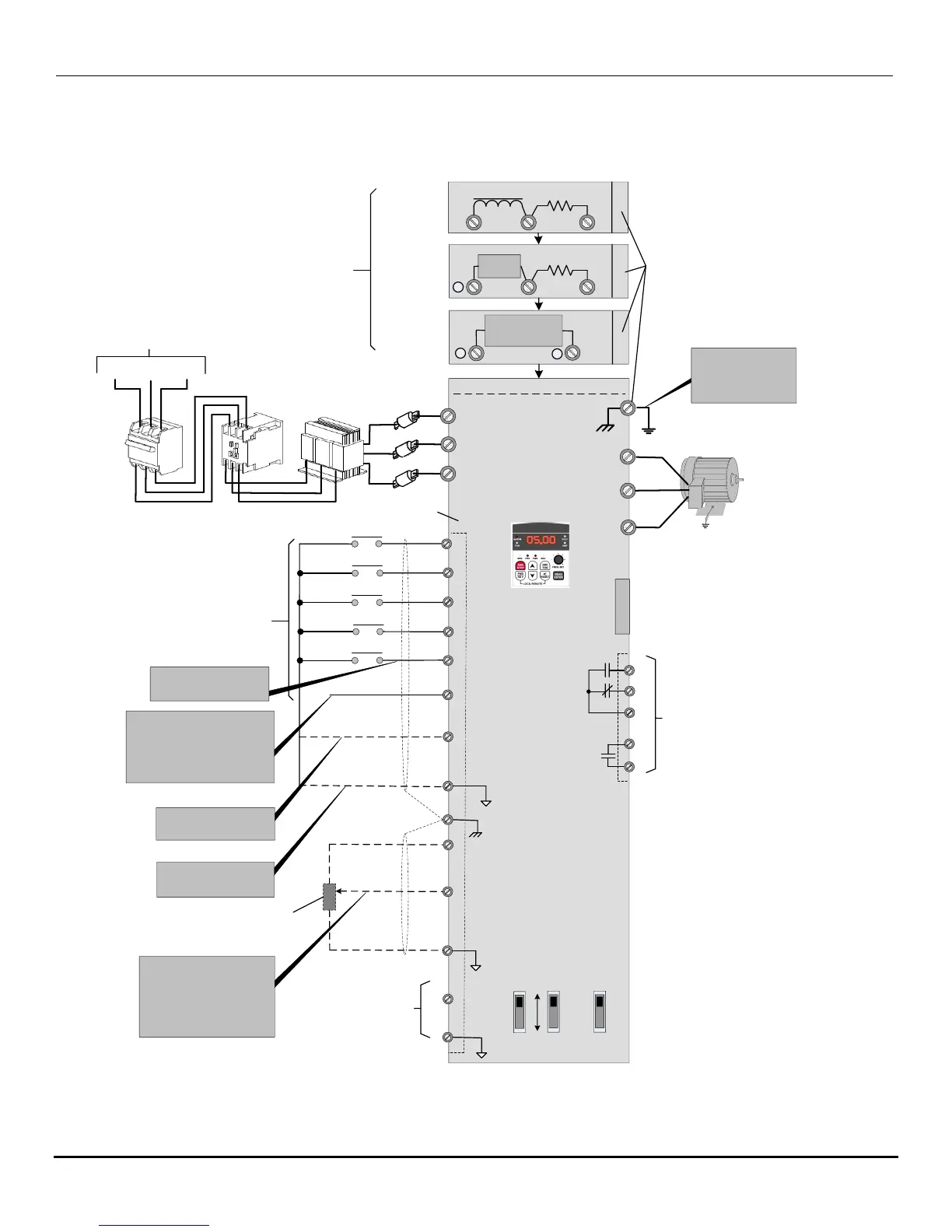
5.0 General Wiring Diagram 1 - 2 HP
T1(U)
T2(V)
T3(W)
L1(R)
L2(S)
L3(T)
RUN / STOP
S1
S2
S3
S4
S5
3 Ø
INDUCTION MOTOR
MULTIFUNCTION
DIGITAL INPUTS
(See parameters A050 – A057)
+10V
AIN / S7
COM
(0V)
E
E
R1A
R1B
R1C
R2A
R2C
N3
INVERTER
SHIELD
SHIELD
N3 General Wiring Diagram
1 - 2 HP and (3-75 HP prior to Version 1.3)
0 - 10 VDC
ANALOG
OUTPUT
(See parameters
A103 & A104)
MULTIFUNCTION RELAY
OUTPUTS
Dry contacts rated
(250 VAC / 30 VDC @ 2A)
(See parameters A105 & A106)
+24V
COM
RUN / STOP or REV / FWD
For SOURCE mode connect
to +24V and set SW1 to the
PNP position.
For SINK mode connect to
COM and set SW1 to the NPN
position. (Factory Default)
+FM
COM
S6 / AI2
(0V)
(0V)
SW1
NPN
PNP
SW3
I
V
SW2
BR
DC Choke
Braking
Resistor
P1
Braking
Resistor
P
_
B1/P
B2
DC Power
Supply
_
DC Power Supply
or
External Braking Unit
+
230V: 0.5 – 10 HP
460V: 1 – 15 HP
230V: 15 – 20 HP
460V: 20 HP
230V: 25 – 40 HP
460V: 25 – 75 HP
NOTE -
GROUND CONNECTION
RESISTANCE TO BE -
230V CLASS: ≤100Ω
460V CLASS: ≤10Ω
PE
E
E
Ground Terminal
Designation
TERMINAL DESIGNATIONS FOR
POWER DEVICE INPUTS FOR
VARIOUS HORSEPOWER.
(See Sec. 7.0 for further details)
CON 1
CON 2
OPTION CARD
CONNECTOR
TM2
TM2
(See Sec. 10.0 for further details)
S5 can be configured for pulse
input. ( A054 = 0019) (See
also parameter A098)
The AIN / S7 input terminal can be
configured as an Analog input:
SW2 = V (0-10VDC) or *(2 - 10VDC)
SW2 = I (0 - 20 mA) or *(4 - 20 mA)
*(See Note)
AIN/S7 can also be configured as a
digital input .
Example – An external pot is
connected to the AIN terminal as
shown providing 0 - 10 VDC input
2K
L1(R)
L2(S)
L3(T)
Fast Acting
Fuses
PE
PE
S6 / AI2 can be configured as a digital
or analog input.
SW3 = V (0-10VDC) or (2 - 10VDC)
SW3 = I (0 - 20 mA) or (4 - 20 mA)
(See parameters *A049, (A050 – A056),
A097 & A154)
*A049 – Version 1.3 or later)
*Note: For versions prior to 1.3, to set AIN (2-10V) or
(4-20mA), parameters A92-A96 were used. For
versions 1.3 or higher it can be set directly with
parameter A154. Also see parameters A050 - A056.
AC Input Voltage

 Loading...


