N3 Drive Operations Manual
(Advanced) Parameter Details; A123 – A128 Cont. & A129 – A137 71
Under Torque:
A124 = 0000: When there is under torque, the inverter will continue to run and flashes “OL4” until the output
torque increases to more than the A127 set value.
= 0001: When there is under torque, the inverter coasts to stop and flashes “OL4”. After the fault clears,
the “Reset” key on the keypad or external reset must be activated to restart the drive.
Note: When parameters A105 and / or A106 (Multifunction output terminal) =15, the relay
Output(s) will be activated on under torque.
3.) Over / Under torque functions are disabled when parameter A123 = 0000 and will only be active when parameter
A123 = 0001 or 0002.
V/f pattern selection (0 – 18): The following fig’s show the various V/f patterns using the parameter settings as
specified.
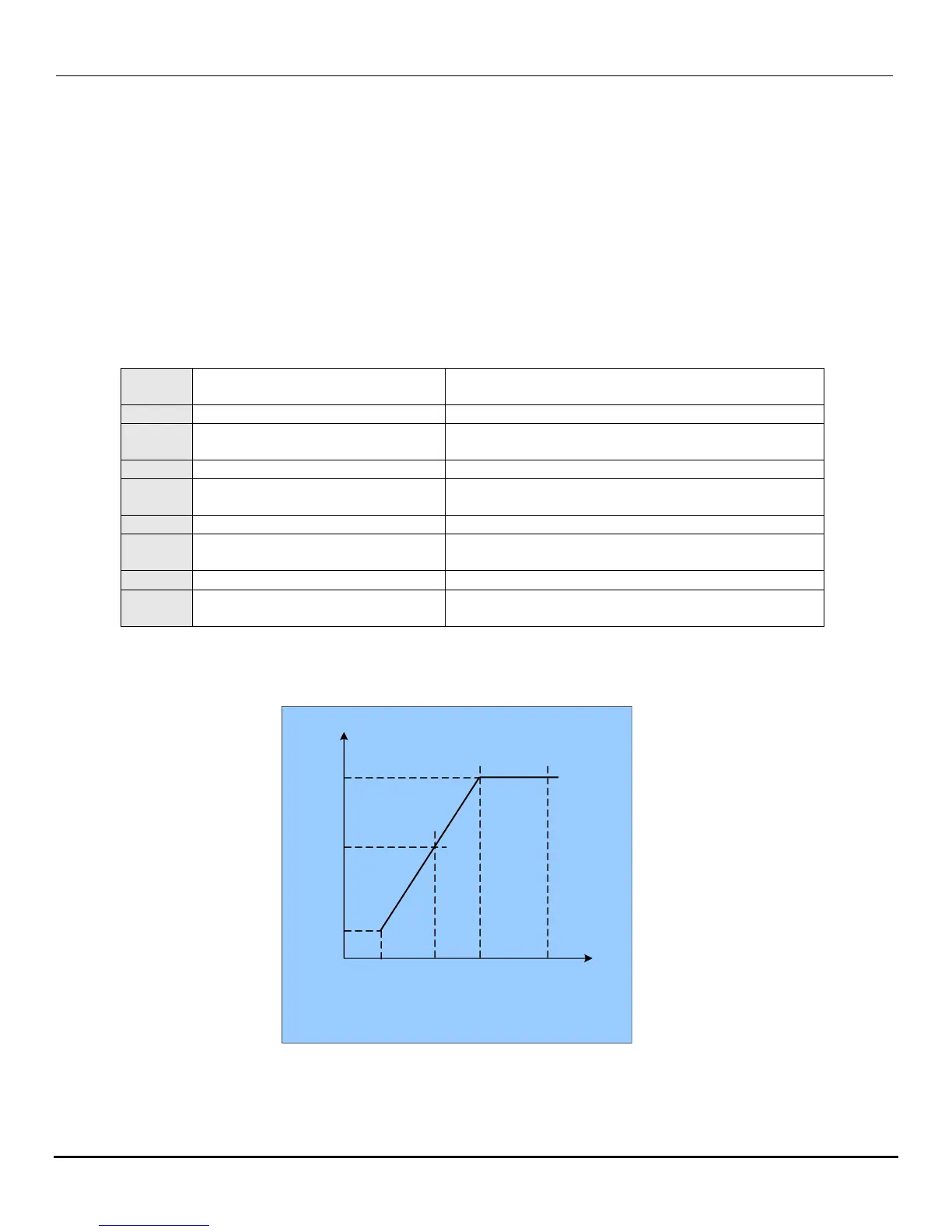
1.) When b009 = 0018, the V/F pattern can be customized in accordance with the parameters A132 – A137 as
shown in the fig. below.
Fig. 19.26
Cont.
Torque boost gain (V/F pattern
modulation)%
Motor no load current(Amps AC)
Motor rated slip
compensation(%)
Max output frequency voltage
ratio(%)
Medium output frequency
Voltage ratio (%)
Min output frequency voltage
ratio (%)
Custom V/f setting
A133
(Vmax.)
A136
A135
(Vmid.)
A137
(Vmin.)
A134
A132
Hz
V %
400 Hz
(max.)
0.10 Hz
(min.)
Hz
(mid.)

 Loading...


