N3 Drive Operations Manual
(Advanced) Parameter Details; A145 – A148 75
A145 / A146: PID the calculated result pluses A146 (the sign of A146 is determined by A145).
A147: Update time for output frequency.
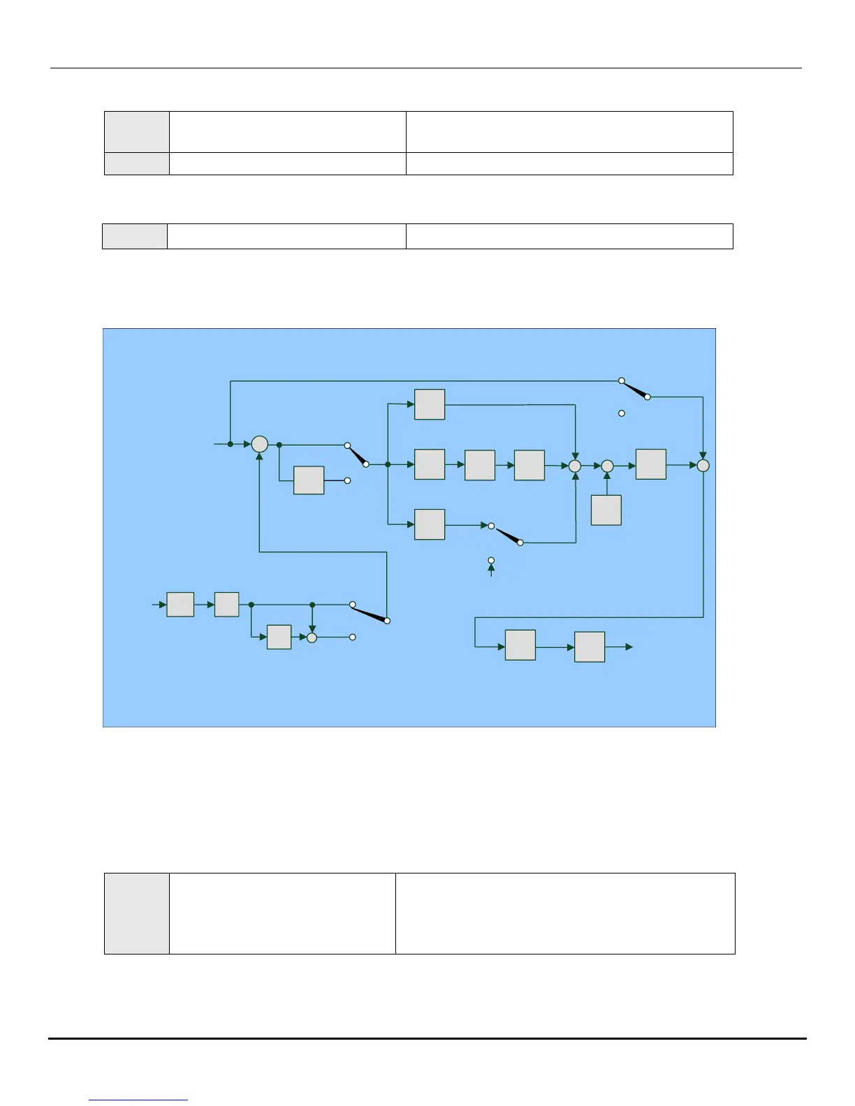
Note: The PID function is available for controlling the output flow, external fan flow and temperature (See fig. below).
Fig. 19.29
1.) To enable PID control, set parameter A049 = 0020 (PID Feedback signal AI2 on TM2).
2.) The set point is the b004 input frequency.
3.) There are two ways to display the PID feedback signal: one is using the keypad display
(b016 = 0001: enable PID feedback display), and the other is using analog output FM+
(A103 = 0005 PID feedback).
A148 = 0: Disable.
A148 = 1: Detect, continue running, and display ‘PDER’.
A148 = 2: Detect, stop, and display ‘PDER’.
0000: Positive Direction
0001: Negative Direction
Output Lag Filter Time (sec.)
Feedback Loss Detection Mode
0000: Disable
0001: Enable – Drive Continues to Operate After
Feedback Loss.
0002: Enable – Drive “STOPS” After Feedback
Loss.
P
I
D
Offset
+/-
A147
PID Delay
Sleep
Mode
PID
Output
A155/A156
Sleep Mode
A145/A146
Deviation
A140=2,4,6,8
Feedback D
-1
+
-
b004
Frequency
Command
(PID Command)
Gain
A140=2,4,6,8
Feedback D
D
Signal
A049
(AI2)=20
PID
Feedback
A154
Feedback
Signal
A141
Feedback
Gain
A140
D gain
+
+
A140=1,3,5,7
Deviation D
A143
Integral Time
A142
Proportion Gain
A140=
3,4,7,8
Reverse
characteristic
+
+
+
A140=1,2,5,6
Forward
characteristic
A144
Ditterential Time
A151
Integral
limit
I
limit
I
reset
+
A140=1,2,3,4
PID Output=PID
PID
Limit
PID Limit
Up=b005
Down=b006
A152
Integral
reset to 0
A140=1,3,5,7
Deviation D
A140=5,6,7,8
PID Output = PID +
Frequency Command
PID block diagram

 Loading...


