App2
(2)Exclusive OR the first 8-bit byte of the message with the low-order byte of the 16-bit CRC
register, putting the result in the CRC register.
(3)Shift the CRC register one bit to the right (toward the LSB), Zero-filling the MSB, Extract
and examines the LSB.
(4)(If the LSB was 0): Repeat Steps(3)(another shift). (If the LSB was 1): Exclusive OR the
CRC register with the polynomial value A001 hex (1010 0000 0000 0001), putting the
result in the CRC register.
(5) Repeat Steps (3) and (4) until 8 shifts been performed. When this is done, a complete 8-bit
byte
Will be processed.
(6) Repeat Steps (2) through (5) for next 8-bit byte of the message, Continue doing this until all
bytes have been processed. The final content of the CRC register is the CRC value.
Placing the CRC into the message: When the 16-bit CRC (2 8-bit bytes) is transmitted in
the message, the Low-order byte will be transmitted first, followed by the high-order byte,
For example, if the CRC value is 1241 hex, the CRC-16 Upper put the 41h, the CRC-16
Lower put the 21h.
CRC calculation application program
UWORD ch_sum ( UBYTE long , UBYTE *rxdbuff ) {
BYTE i = 0;
UWORD wkg = 0xFFFF;
while ( long-- ) {
wkg ^= rxdbuff++;
for ( i = 0 ; i < 8; i++ ) {
if ( wkg & 0x0001 ) wkg = ( wkg >> 1 ) ^ 0xa001;
else wkg = wkg >> 1;
}
}
return( wkg );
}
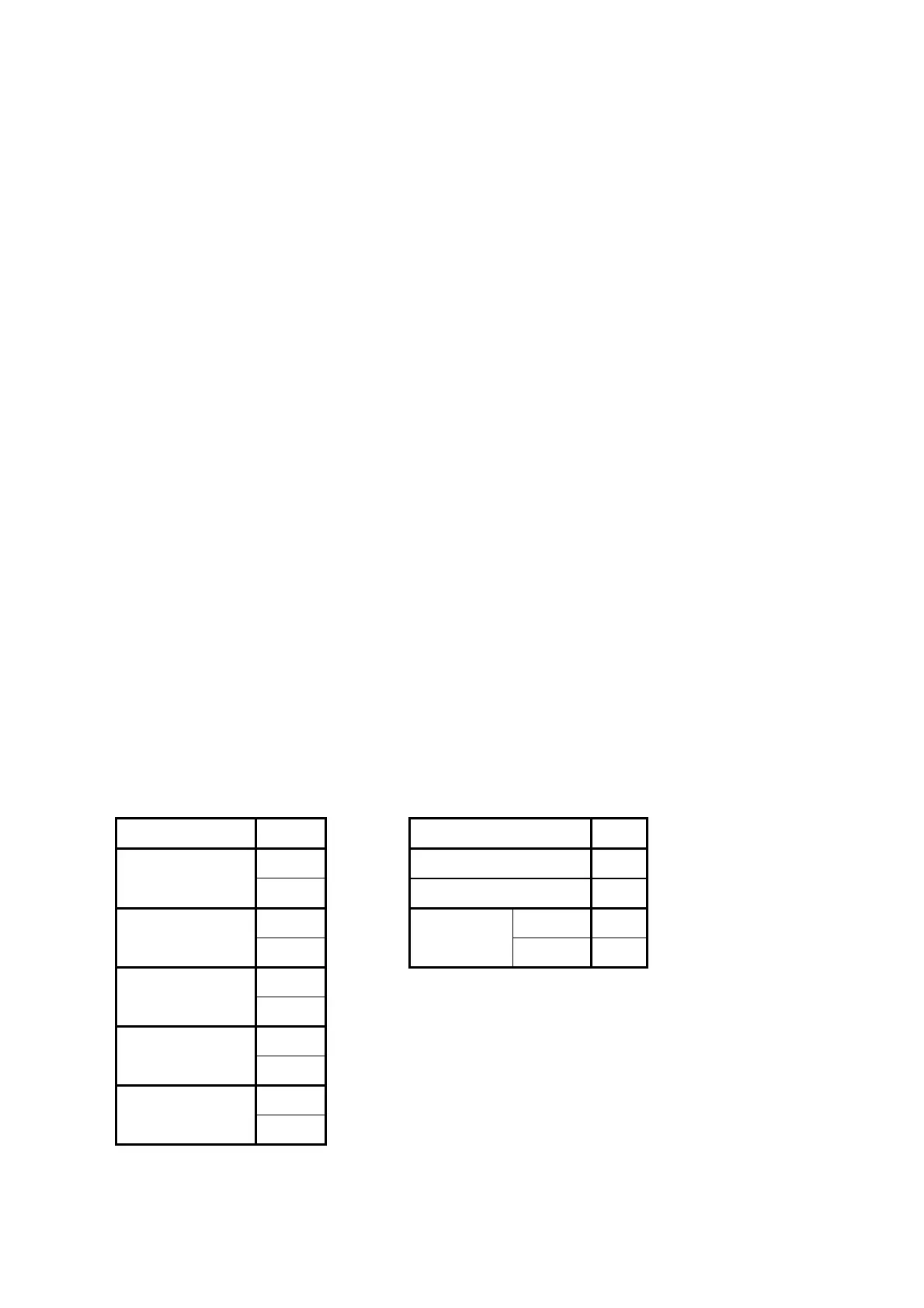
3. Error code
ASCII Mode RTU Mode
STX ‘:’
SLAVE Address 02H
Address
‘0’ Function
83H
‘1’ Exception code
52H
Function
‘8’
CRC-16
High C0H
‘6’
Low CDH
Exception
code
‘5’
‘1’
LRC Check
‘2’
‘8’
END
‘CR’
‘LF’
Under communication linking, the driver responses the Exception Code and send Function Code
AND 80H to main system if there is error happened.