3-12
3.6 Description of connection terminals
Descriptions of main circuit terminals
Symbol Description
L1
Main power input. Model 401/402/403/405:L1/L2/L3
L2
L3
BR
Braking resistor connection terminal: Used in
applications when it is required to stop a high inertia load
rapidly. (refer to specifications of the braking resistor)
For
400V class:1~5HP.
P1
U
Inverter outputs V
W
Descriptions of S310 control circuit terminals
Symbol
Description
RB Normal close contact
Multifunctional output
terminals
Contact rated capacity:
(250VAC/1A or30VDC/1A)
Contact using descri
to parameters 01-09)
RA Normal open contact
10V
Frequency knob (VR) power source terminal (pin 3)
AIN
Analog signal input terminal 0~10(2~10)VDC/0~20(4~20)mA, Select by JP1.
AVI
Analog signal input terminal 0~10(2~10)VDC(S310+-203H1/401/402/403/405-H3)
ACI
Analog signal input terminal 0~20(4~20)mA(S310+-203H1/401/402/403/405-H3)
COM
Common for digital input signal for S1~S5 input.
FM+
The positive multifunction analog output signal for multifunction (refer to parameter 2-12
description), the signal for output terminal is 0-10VDC (below 2mA).
S1
multifunction input terminals(refer to parameter 1-00~1-05 description)
S2
S3
S4
S5
A (+) RS485 communication applications
B (- ) RS485 communication applications
SG Ground(RS485)
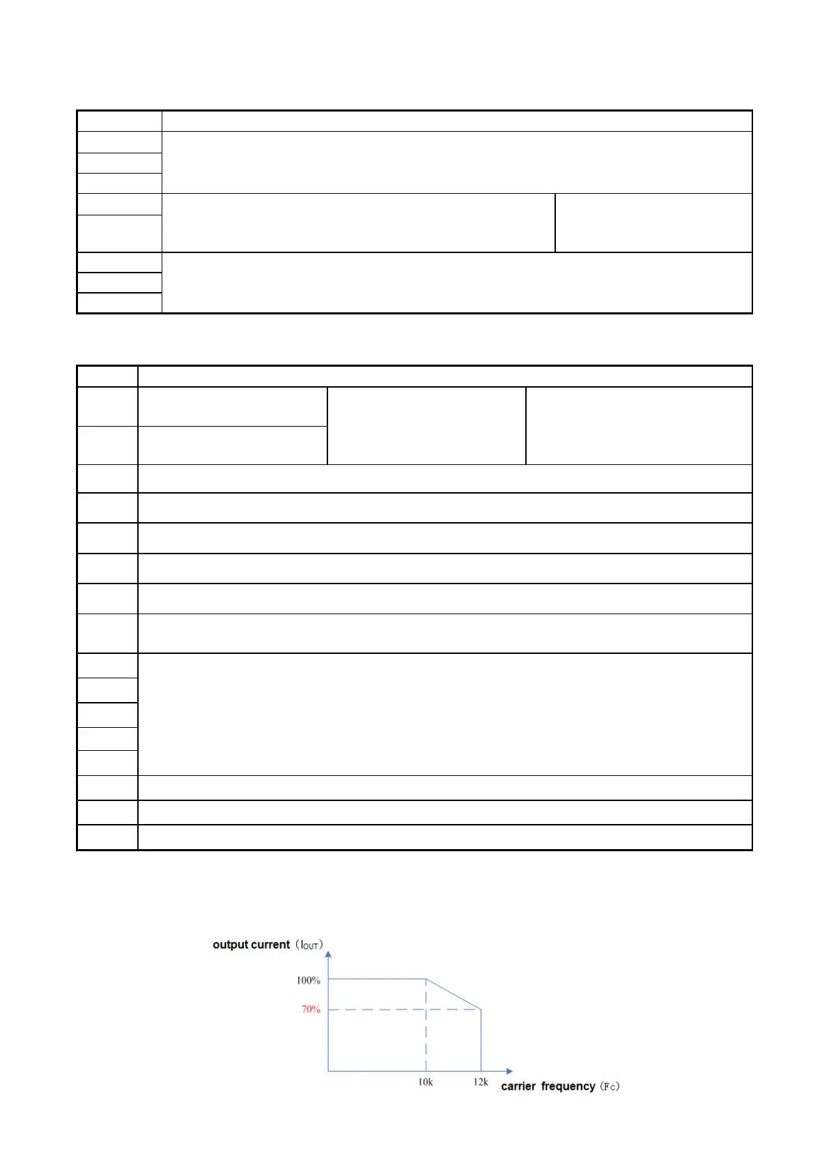
Inverter Derating Based on Carrier Frequency.
401/402/405 does not need Derating.
403 need Derating according to the following curve.
 Loading...


