Digital linearity of sensor signal
Electronic part protective treatment
Internal battery for RTC power supply
DISPLAY AND DATA MANAGEMENT
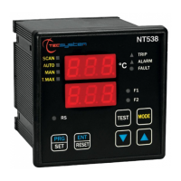
2 x 13 mm displays with 3 digits to display temperatures, messages and channels
3 LEDs to display the state of the alarms of the selected channel (ALARM-TRIP-FAULT)
4 LEDS selection of display mode (SCAN-AUTO-MAN-T-MAX)
2 LEDs to display the state of FAN1 and FAN2
Temperature control from 0°C to 240°C (*)
2 alarm thresholds for channels 1-2-3
2 alarm channels for channel 4
2 ON-OFF thresholds FAN 1 and FAN 2 ventilation
Sensor diagnostics (Fcc-Foc-Fcd)
Data memory diagnostics (Ech)
Access to programming through front keyboard
Automatic exit from programming, display and relay test after 1 minute of inactivity
Incorrect programming warning
Selection between channels automatic scanning, hottest channel or manual scanning
Storage of maximum temperatures reached by channels and alarm status
Front key to reset the alarms
WEB SERVER Wi-Fi Function
Internal clock keeping in STATION (NTP server) and ACCESS POINT mode
Automatic sending of alarm activation e-mails
Periodic sending of channel statistics reports
(*) On request, reading version -40°C to 200°C with alarm temperature control from 0°C to 200°C