CONTROLLER USER’S GUIDE
NOVA DVR (SWITCHED RELUCTANCE) DRIVE
Control Software versions 4.54x
Interface Software version s03
Teknatool International
13
th
July 2006
1.0 INTRODUCTION
1.1 General
This guide contains the basic information on use of the Digital Variable Reluctance (DVR) electrical drive
for DVR 3000/XP lathe.
1.2 Overview
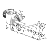
The DVR integrated electrical drive system contains the DVR motor with the Rotor Position Sensor
(RPS), the drive control board and the human-machine interface (HMI). The control board, RPS and
HMI represent the control system of the drive. The DVR is connected with the control board by six power
wires and RPS cable.
The control board contains power input devices - input rectifier, power factor corrector with the DC link
reactor, three-phase inverter and the control circuit based on the 16-bit Infineon microcontroller.
The HMI contains the interface board, the LCD and keyboard. The interface board is based on the 8051
family Atmel microcontroller and connected with the control board through the insulated serial RS232
interface.
Both microcontrollers have flash program memory. The interface board microcontroller also contains the
EEPROM memory in order to change and store the drive parameters. The control system has been
specifically designed for control flexibility and to provide optimal drive performance.
2.0 MAIN PARAMETERS AND FEATURES
The motor type – Switched Reluctance Motor (DVR)
Nominal operating output power –1.25 -1.5 kW ( 2 HP 220V )
Power supply range: 115V 60Hz/ 230V 50 Hz
Power factor correction: PF 0.95
Speed range: 100 – 3500 rpm
Smooth speed setting by keys
5 preset (favorite) speeds with save function.
PI speed controller with adaptive coefficients
3 preloaded coefficient curves: SOFT, NORMAL and HARD
Load inertia measurement for improving the PI speed controller coefficients
Reverse function
Torque and speed ramp functions
Overload protection
Under-voltage / PFC fault protection