Theory of Operation-314 Service
Other horizontal deflection signals can be connected to
the horizontal amplifier by using the Ext Horizontal mode
of operation. For the Ext Horizontal mode, the trigger
preamplifier is used as a high-impedance-input amplifier,
and when so used, the sweep generator is disabled.
CRT and Power Supply
The crt circuit contains the controls necessary for
operation of the cathode-ray tube. Trace storage is
accomplished by the Storage circuit. The Power Supply
and crt circuits provide all the voltages necessary for
operation of the instrument.
Calibrator
The Calibrator circuit provides a square-wave output
with accurate amplitude, which can be used to check
calibration of the vertical portion of the instrument and for
probe compensation.
CIRCUIT OPERATION
This section provides a description of the electrical
operation and relationship of the circuits in the
314.
The
theory of operation for circuits unique to this instrument is
described in detail in this discussion. Circuits that are
commonly used in the electronics industry are not
described in detail.
CHANNEL
1
PREAMP
0
0
AND CALIBRATOR
@
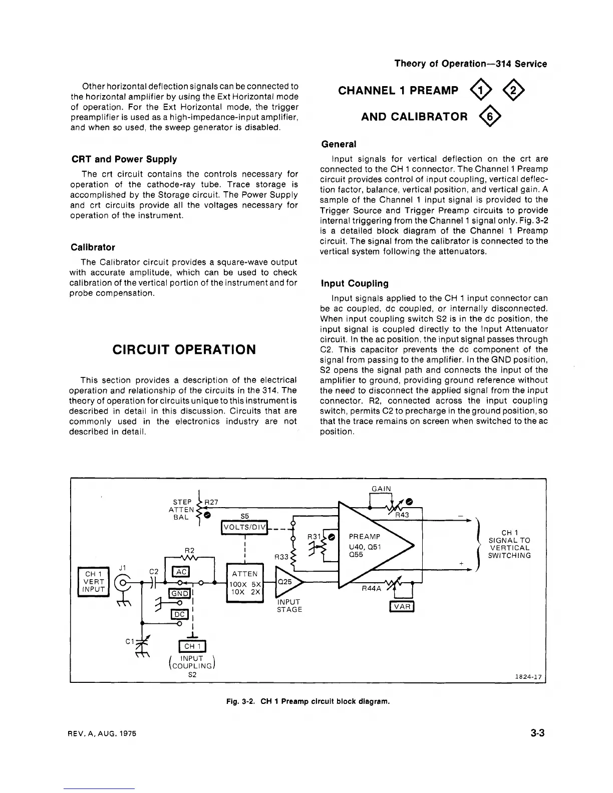
General
lnput signals for vertical deflection on the crt are
connected to the CH
1
connector. The Channel
1
Preamp
circuit provides control of input coupling, vertical deflec-
tion factor, balance, vertical position, and vertical gain. A
sample of the Channel
1
input signal is provided to the
Trigger Source and Trigger Preamp circuits to provide
internal triggering from the Channel
1
signal only. Fig. 3-2
is a detailed block diagram of the Channel
1
Preamp
circuit. The signal from the calibrator is connected to the
vertical system following the attenuators.
lnput Coupling
lnput signals applied to the CH
1
input connector can
be ac coupled, dc coupled, or internally disconnected.
When input coupling switch
S2
is in the dc position, the
input signal is coupled directly to the lnput Attenuator
circuit. In the ac position, the input signal passes through
C2. This capacitor prevents the dc component of the
signal from passing to the amplifier. In the
GND
position,
S2 opens the signal path and connects the input of the
amplifier to ground, providing ground reference without
the need to disconnect the applied signal from the input
connector. R2, connected across the input coupling
switch, permits C2 to precharge in the ground position, so
that the trace remains on screen when switched to the ac
position.
I
GAIN
-
b
+
+
STAGE
CH
1
SIGNAL TO
VERTICAL
SWITCHING
Fig.
3-2.
CH
1
Preamp circuit block diagram.
REV.
A,
AUG.
1975