Theory of Operation-314 Service
CHANNEL 1
PREAMP
CHANNEL 2
PREAMP
VERTICAL
SIGNAL TO
COMMON-BASE
AMPLIFIER
+
+6
V +6 V
+6
V t6
V
R
120 R115 R125
R 130
4b
$
-
CR120
CR130
R131
FORWARD-BIASED
R121
REVERSE-BIASED
0
-6 V
0
A
I
I
O
SWITCHES SET TO
I
I
,
-
- -
-
-
-
-
-
-
-
-
-
.,
I
(DISPLAY CHANNEL 2)
I
I
I
I
I
i
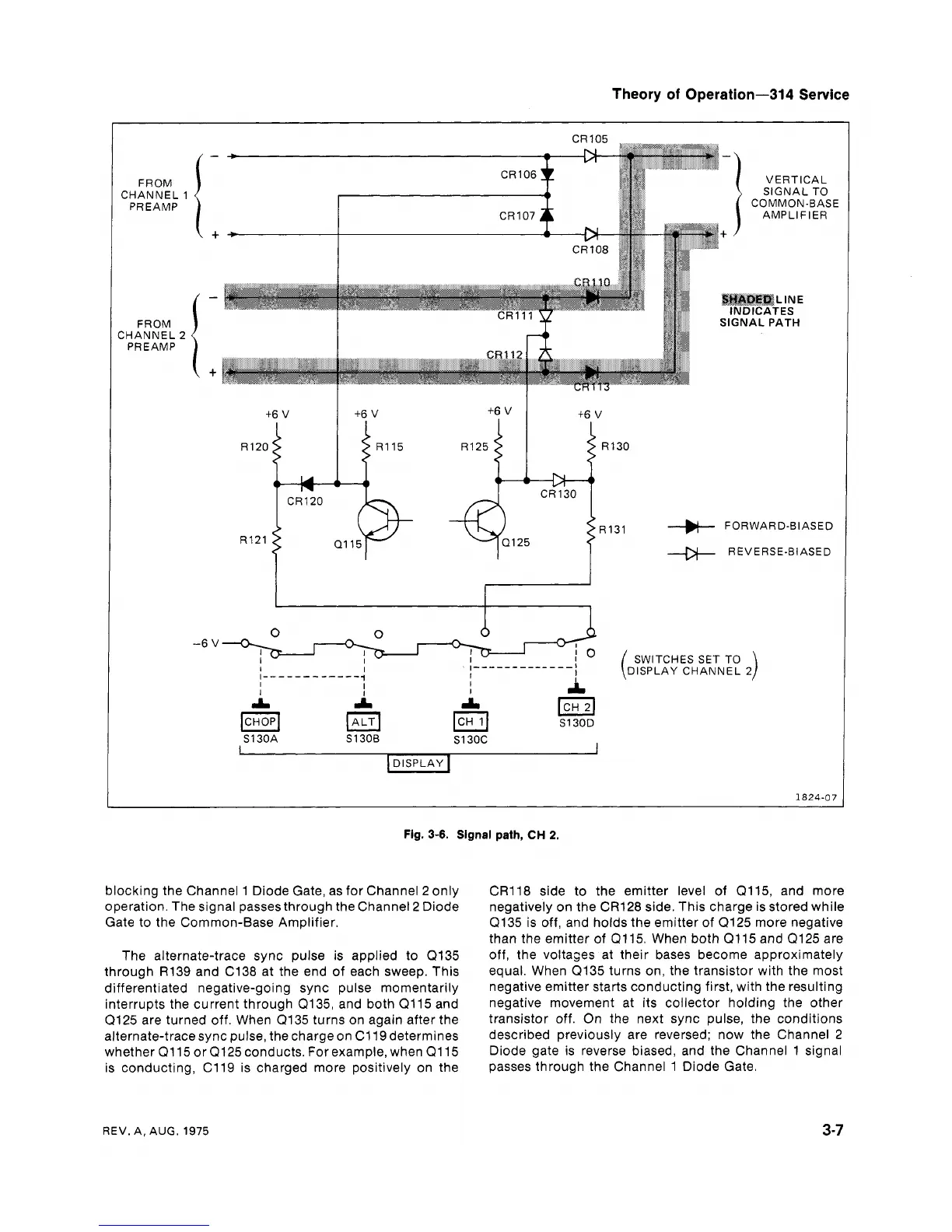
Fig.
3-6.
Signal path,
CH
2.
blocking the Channel 1 Diode Gate, as for Channel 2 only
operation. The signal passes through the Channel
2
Diode
Gate to the Common-Base Amplifier.
The alternate-trace sync pulse is applied to
(2135
through R139 and C138 at the end of each sweep. This
differentiated negative-going sync pulse momentarily
interrupts the current through Q135, and both Q115 and
Q125 are turned off. When Q135 turns on again after the
alternate-trace sync pulse, the charge on C119 determines
whether
Q115 or (2125 conducts. For example, when Q115
is conducting,
C119 is charged more positively on the
CR118 side to the emitter level of (2115, and more
negatively on the CR128 side. This charge is stored while
Q135 is off, and holds the emitter of Q125 more negative
than the emitter
of
Q115. When both Q115 and Q125 are
off, the voltages at their bases become approximately
equal. When Q135 turns on, the transistor with the most
negative emitter starts conducting first, with the resulting
negative movement at its collector holding the other
transistor off. On the next sync pulse, the conditions
described previously are reversed; now the Channel 2
Diode gate is reverse biased, and the Channel 1 signal
passes through the Channel 1 Diode Gate.
REV. A,
AUG.
1975