Theory of Operation-314 Service
VERTICAL
CHANNEL
1
+
SIGNAL TO
PREAMP COMMON-BASE
AMPLIFIER
I I I
CRllO
-
-
i
I
N
CHANNEL
2
PREAMP
hl
+
&
LINE
INDICATES
SIGNAL
PATH
FORWARD-BIASED
REVERSE-BIASED
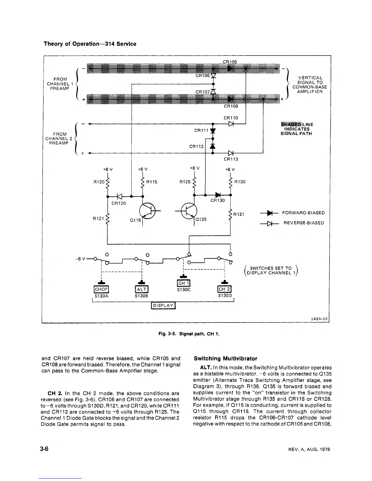
Fig.
3-5.
Signal path,
CH
1.
and CR107 are held reverse biased, while CR105 and
CR108 are forward biased. Therefore, the Channel 1 signal
can pass to the Common-Base Amplifier stage.
CH
2.
In the CH 2 mode, the above conditions are
reversed (see Fig. 3-6). CR106 and CR107 are connected
to -6 volts through S130D, R121, and CR120, whileCR111
and CR112 are connected to +6 volts through R125. The
Channel 1 Diode Gate blocks the signal and the Channel 2
Diode Gate permits signal to pass.
Switching Multivibrator
ALT.
In this mode, the Switching Multivibratoroperates
as a bistable multivibrator. -6 volts is connected to Q135
emitter (Alternate Trace Switching Amplifier stage, see
Diagram
3),
through R136. (2135 is forward biased and
supplies current to the "on" transistor in the Switching
Multivibrator stage through R135 and CR118 or CR128.
For example, if Q115 is conducting, current is supplied to
(2115 through CR118. The current through collector
resistor R115 drops the
CR106-CR107 cathode level
negative with respect to the cathode of
CRlO5 and CR108,
REV.
A.
AUG.
1975