Maintenance-314 Service
h. Lift the front of the board out. If it is necessary to
replace the circuit board, the remaining wires must be
unsoldered. Record the position and color of each wire
and shield and the point to which each lead is connected.
i. To replace, reverse the foregoing procedure.
Trigger Switch Circuit Board (Assembly A3)
a. Remove the Vertical circuit board as outlined in
Vertical Circuit Board instructions.
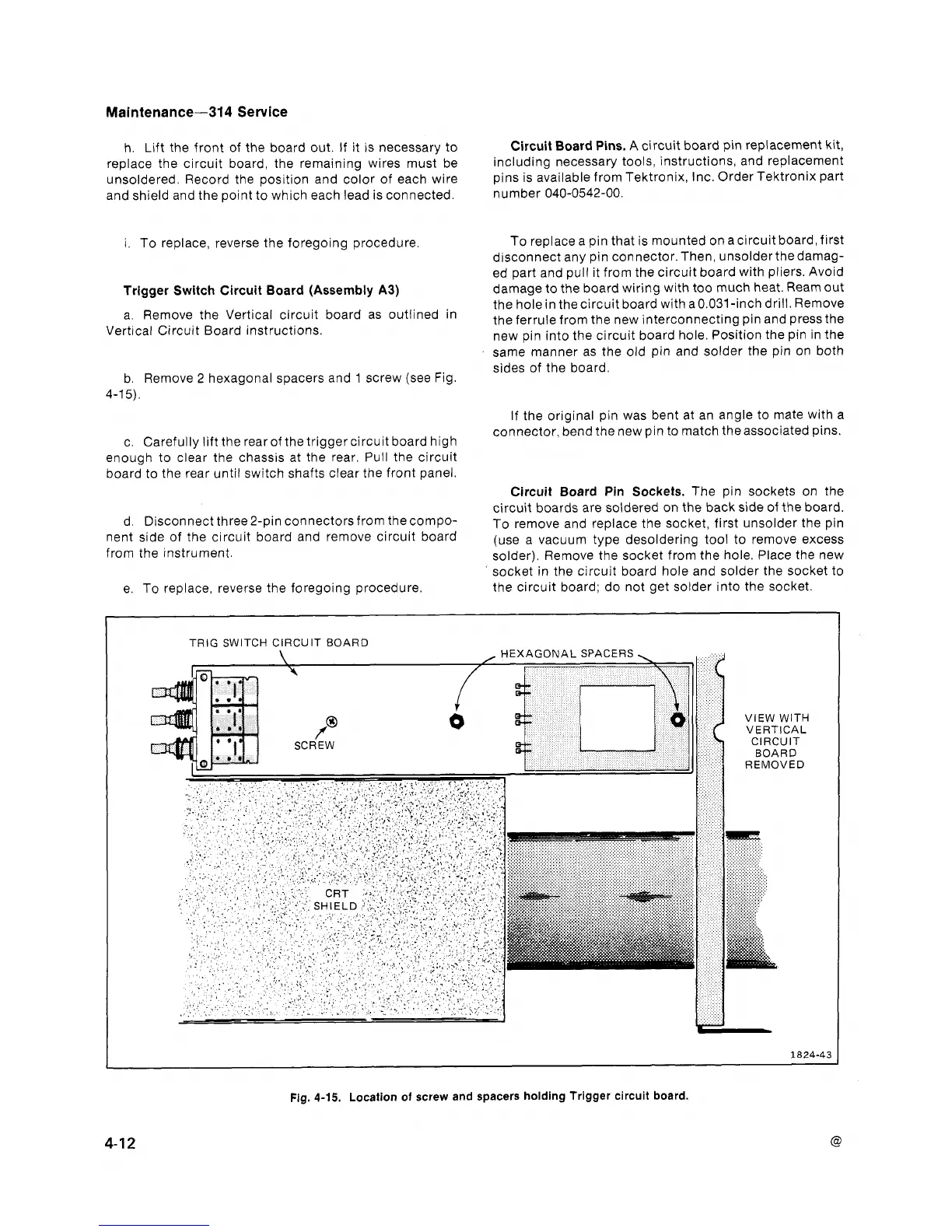
b. Remove
2
hexagonal spacers and
1
screw (see Fig.
4-1
5).
c. Carefully lift the rearof the trigger circuit board high
enough to clear the chassis at the rear. Pull the circuit
board to the rear until switch shafts clear the front panel.
d. Disconnect three2-pin connectorsfrom thecompo-
nent side of the circuit board and remove circuit board
from the instrument.
e. To replace, reverse the foregoing procedure.
Circuit Board Pins.
A
circuit board pin replacement kit,
including necessary tools, instructions, and replacement
pins is available from Tektronix, Inc. Order Tektronix part
nu m ber 040-0542-00.
To replace a pin that is mounted on acircuit board, first
disconnect any pin connector.Then, unsolderthedamag-
ed part and pull it from the circuit board with pliers. Avoid
damage to the board wiring with too much heat. Ream out
the hole in thecircuit board with a0.031-inch drill. Remove
the ferrule from the new interconnecting pin and press the
new pin into the circuit board hole. Position the pin in the
same manner as the old pin and solder the pin on both
sides of the board.
If the original pin was bent at an angle to mate with a
connector, bend the new pin to match theassociated pins.
Circuit Board
Pin
Sockets. The pin sockets on the
circuit boards are soldered on the back side of the board.
To remove and replace the socket, first unsolder the pin
(use a vacuum type desoldering tool to remove excess
solder). Remove the socket from the hole. Place the new
socket in the circuit board hole and solder the socket to
the circuit board; do not get solder into the socket.
Fig.
4-15.
Location of screw and spacers holding Trigger circuit board.