Section
5-314
Service
PERFORMANCE CHECKICALIBRATION
PERFORMANCE CHECK
Introduction
This section is divided into two parts: a Performance
Check and a Calibration Procedure. Each part containsan
index to aid in locating a particular step. The Equipment
Required list applies to both sections, but the equipment
required for calibration only is marked with a footnote.
USING THE PROCEDURE
Index
To aid in locating steps, an index precedes the
Performance Check procedure.
Partial Procedure
The procedure checks completely the Performance
Requirements. If you do not require the full available
performance from the instrument, the required instrument
list may be shortened accordingly.
A partial performance check may be desirable after
replacing components or partial recalibration. To check a
part of the instrument, refer to the Equipment Required list
preceding that portion to be performed.
Control Settings
To aid in setting up a given test, each
314
control or
switch that is named on the front, side, or rear panel is
shown in the Control Settings in capital letters. Those
314
controls or switches that have an implied function, such as
Source, Coupling, etc., have only the first letter capitaliz-
ed.
Control and switch settings of test equipment have the
first letter capitalized.
TEST
EQUIPMENT
REQUIRED
The test equipment required listed in Table
5-1
is
required for complete check and adjustment of this
instrument. Test equipment specifications given in Table
5-1
are the minimum required to meet instrument
specifications listed in the Specification (Section
1).
Detailed operating instructions for test equipment are not
included in this procedure. Refer to the Test Equipment
instruction manual if more information is needed.
Special Calibration Fixtures
Special calibration fixtures are used only when they
facilitate instrument calibration. These fixtures are
available from Tektronix,
Inc. Order by part number from a
Tektronix Field Office or representative.
Calibration Equipment Alternatives
Test equipment listed in the Examples of Applicable
Test Equipment column, Table
5-1,
is required toadjust or
check the instrument. The procedures are based on the
first item of equipment shown as an example. If equipment
issubstituted, control settings or test setup may need to be
altered. If the exact equipment item given as an example is
not available, refer to the specifications column to deter-
mine if other equipment may be substituted.
Items in column
1
having a superscript
1,
are used only
in the Adjustment procedure.
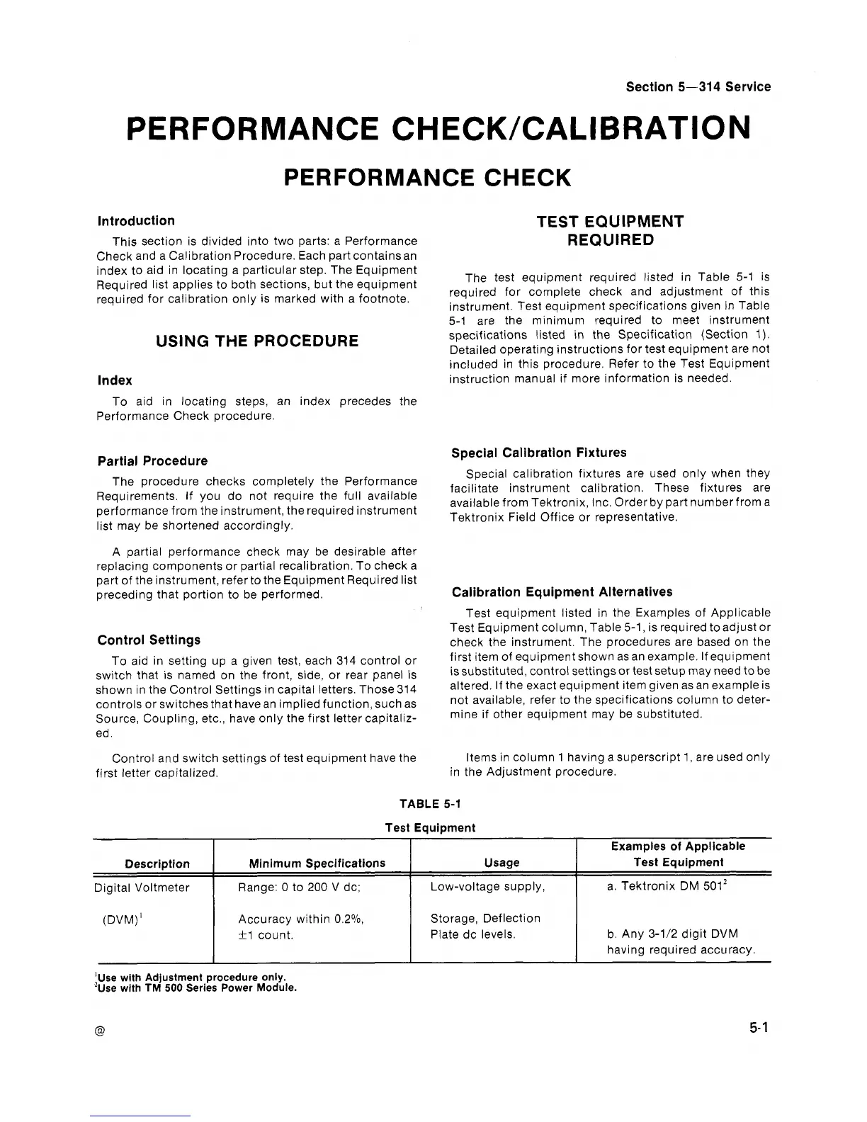
TABLE
5-1
Test Equipment
(DVM)'
Examples of Applicable
Test Equipment
a. Tektronix DM
5012
Usage
Low-voltage supply,
Description
Digital Voltmeter
'use with Adjustment procedure only.
2~se with
TM
500
Series Power Module.
Accuracy within 0.2%
+1
count.
Minimum Specifications
Range: 0 to
200
V dc;
Storage, Deflection
Plate dc levels.
b. Any
3-1/2
digit DVM
having required accuracy.