Reference
3-60
370B User Manual
Common Measurements for Zener Diodes.
V
Z
and I
R
To measure Zener voltage or reverse current, insert the diode cathode in the
emitter terminal of the test socket and the anode of the diode in the collector
terminal. Apply voltage to the device with the VARIABLE COLLECTOR
SUPPLY control. For measurements of small amounts of reverse current, set
the POLARITY to LEAKAGE.
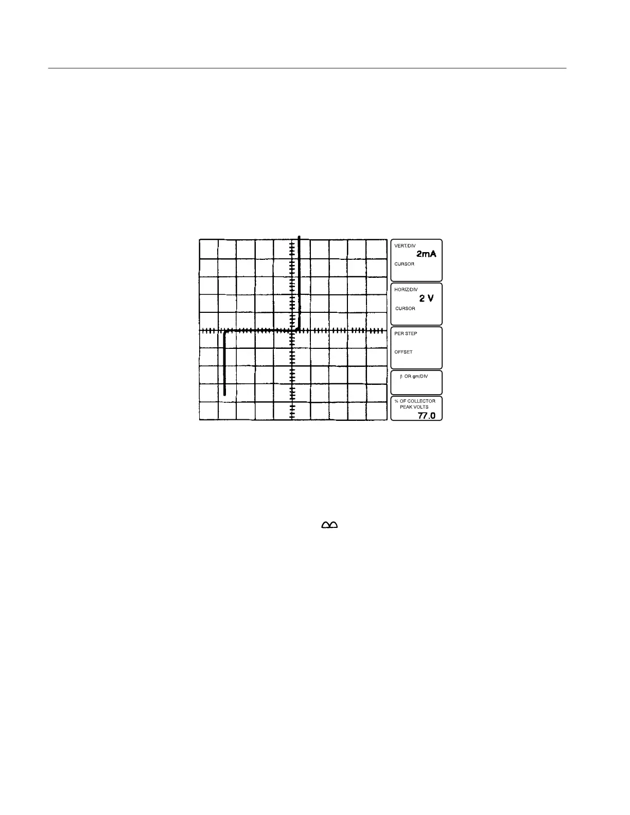
Figure 3-38: Zener Diode Curve
I
F
and V
F
Current and voltage in the forward direction are measured in the same
manner as in the reverse direction, except that the Collector Supply
POLARITY is set to +
. For a display of currents and voltages in both
directions, set the POLARITY to AC.
 Loading...