Reference
370B User Manual
3-59
Common Measurements for Signal Diodes and Rectifying Diodes.
I
F
and V
F
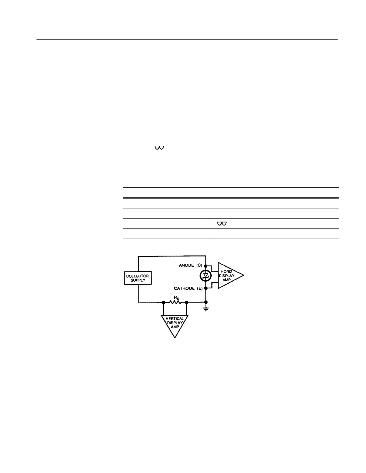
To measure forward current and voltage, insert the cathode of the diode in
the emitter terminal of the test socket and the anode of the diode in the
collector terminal, Apply voltage to the device with the VARIABLE
COLLECTOR SUPPLY control.
I
R
and V
R
Current and voltage in the reverse direction are measured in the same manner
as in the forward direction except that the Collector Supply POLARITY is
set to –
. To measure small amounts of reverse current, set the Collector
Supply POLARITY to – LEAKAGE.
Control Required setting
HORIZONTAL COLLECTOR
MAX PEAK POWER WATTS Less than maximum power rating of device.
COLLECTOR SUPPLY POLARITY -
CONFIGURATION EMITTER COMMON BASE SHORT
Figure 3-37: Zener Diode Configuration Diagram
Zener Diode
 Loading...