Reference
3-16
370B User Manual
. The following ten steps require the optional FET adapter. If you do not
have an adapter on hand, either proceed to step 32, or insert a long-lead FET
into the transistor adapter with the source, gate, and drain leads corresponding
to the emitter, base and collector leads.
22. Open the protective cover, then remove the transistor adapter. (Leave the
transistor in the adapter). Install the A1009 FET adapter (optional) in the
front panel jacks and place an N-channel junction FET into the right test
socket of the adapter. If you have no A1009 FET adapter, use the A1007
adapter, inserting D,G, and S leads into C, B, and E sockets, respectively.
23. Close the protective cover.
24. Change the Memory Index to 1, then press the Setup RECALL button to
initialize the 370B.
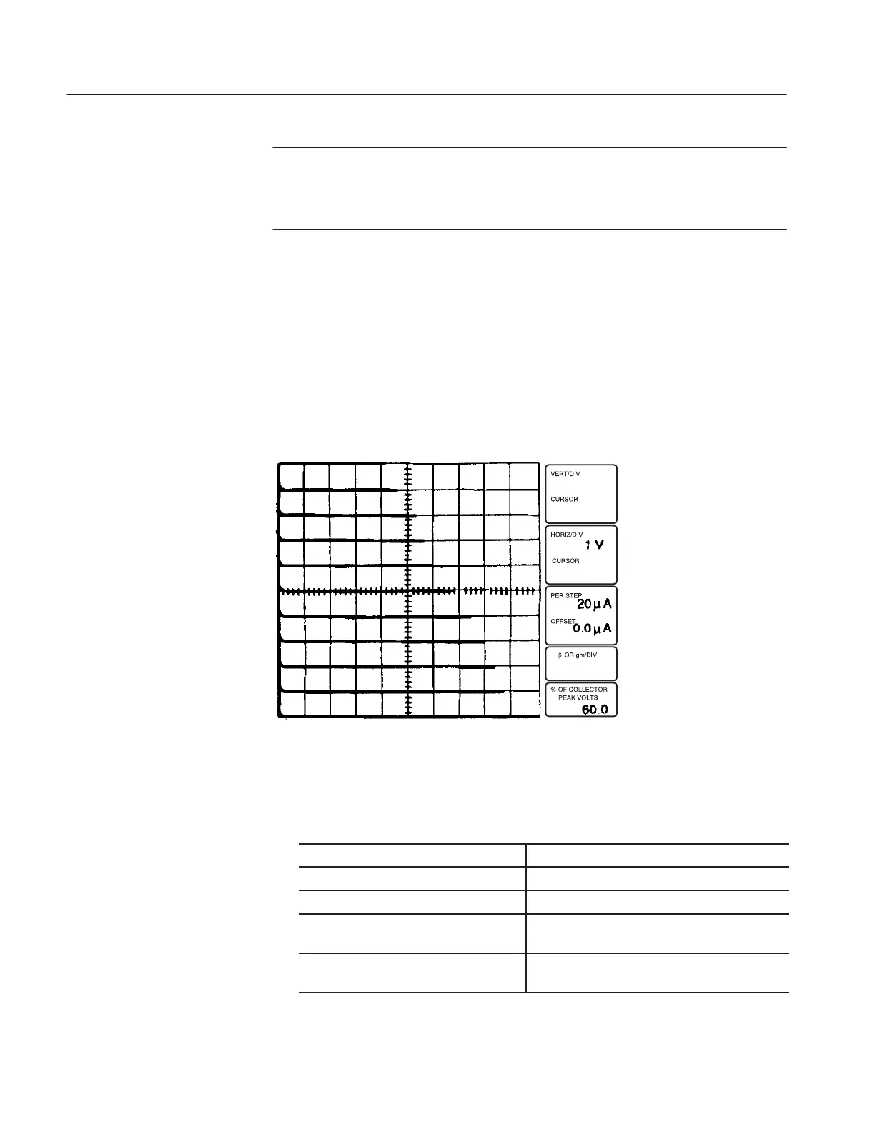
Figure 3-11: I
B
vs. V
CE
25. Set the 370B controls as follows:
LEFTĆRIGHTĆSTANDBY RIGHT
VERTICAL CURRENT/DIV About 1/10 of the rated drain current
Step Generator Output Mode VOLTAGE
STEP AMPLITUDE To appropriate value (depending on the
characteristic of the FET)
Collector Supply
MAX PEAK POWER WATTS
Within the power dissipation rating of the
transistor
26. Set the OUTPUTS breaker to the ENABLED position.