Reference
370B User Manual
3-17
27. Turn the VARIABLE COLLECTOR SUPPLY control slowly clockwise.
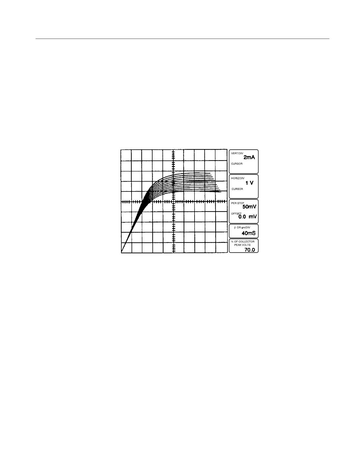
Note the display of drain current vs drain-source voltage with voltage steps
applied to the gate (see Figure 3–12). Since the steps applied to the gate are
positive-going, the curves displayed represent enhancement mode operation
of the FET. (Set number of steps to zero to display the curve obtained with
zero volts applied to the gate, then set number of steps to 10.)
28. Press the Step Generator POLARITY INVERT button (red LED turns on)
and note the display of the depression mode of FET operation. Press the Step
Generator POLARITY INVERT button for a normal display.
Figure 3-12: Display of FET commonĆsource characteristic curves: I
D
vs V
DS
for 10
steps of gate voltage.
29. Set the OUTPUTS breaker to the DISABLED position, then open the
protective cover.
30. Remove the FET test adapter and replace it with the A1007 transistor test
adapter (with the transistor still installed).
31. Close the protective cover.
32. Making sure that the Memory Index is set to 1, press the Setup RECALL
button to initialize the 370B.