Reference
370B User Manual
33. Set the 370B controls as follows:
LEFTĆRIGHTĆSTANDBY RIGHT
VERTICAL CURRENT/DIV About 1/10 of the rated collector current
HORIZONTAL VOLTS/DIV 1 V COLLECTOR
Collector Supply
MAX PEAK POWER WATTS
Within the power dissipation rating of the
transistor
34. Set the OUTPUTS breaker to the ENABLED position.
35. Turn the VARIABLE COLLECTOR SUPPLY control clockwise for a
full-length trace, then turn the STEP AMPLITUDE control clockwise until
a step waveform appear on the CRT. Set the STEP AMPLITUDE for a 1 to
2 division step waveform.
36. Use the Cursor selection buttons to select the DOT cursor.
37. Use the Position Control buttons to move the cursor to the desired point on
the characteristic curve (see Figure 3–13). The figure now displayed in the b
OR gm/DIV readout is the h
FE
of the device under test.
38. Use the Cursor selection buttons to select the
Window cursor.
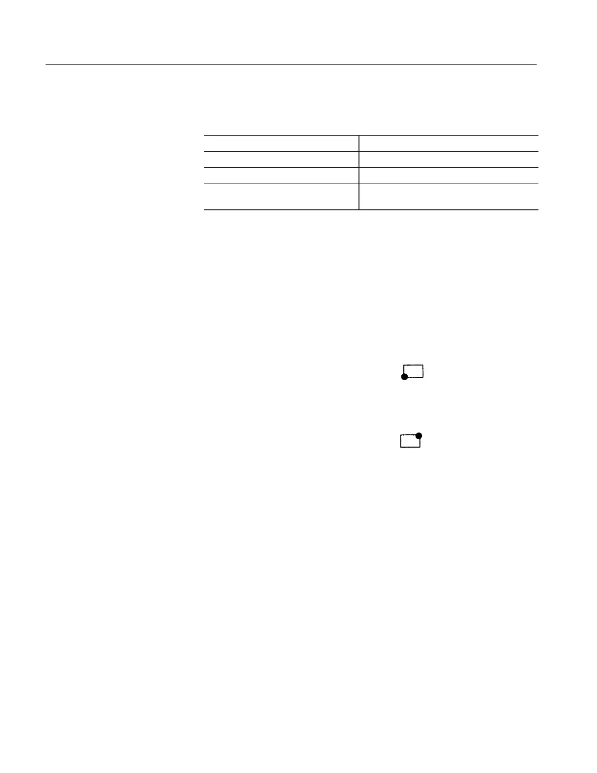
39. Use the Position Control buttons (up, down, left, right) to position the bright
dot, in the lower left corner of the cursor window, at any point on the
characteristic curve.
40. Use the Cursor selection buttons to select the
Window cursor.
41. Press the left Position Control button to narrow the Cursor window into a
straight vertical line.
42. Use the up or down Position Control buttons to position the cursor’s bright
dot on an adjacent characteristic curve (see Figure 3–14). The figure now
displayed in the b OR gm/DIV readout is the hFE of the device under test.