Tutorials
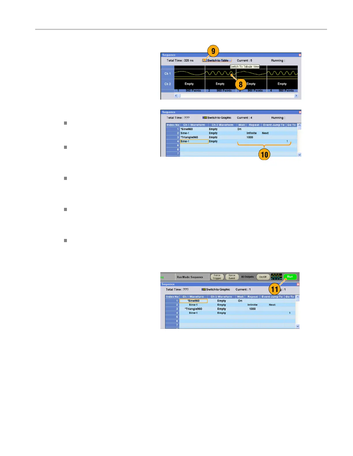
8. The copied waveform is pasted to
index 2.
9. Click the Switch to Table icon to change
the display to
Tabular view.
10. Set the foll
owing sequence parameters:
Index 1: Wai
t Trigger On
The sequence waits for a trigger
before generating the first element.
Index 2: Repeat count Infinite
The sequen
ce infinitely generates
the Sine-1 waveform until an event
occurs.
Index 2: Event Jump To Next
When the i
nstrument receives an
event signal, the sequence jumps to
next element.
Index 3: Repeat count 1000
The sequ
ence repeats the
*Triangle960 waveform 1000
times.
Index 4: Go To 1
The seq
uence jumps to index
number 1 after generating index
number 4 waveform.
11. Click the Run button to confirm that the
seque
nce w orks properly. The animation
window next to the Run button will be
activated when the instrument is in the
runn
ing state.
AWG5000 and AWG7000 Series Quick Start User Manual 83

 Loading...


