EasyManuals Logo

Tektronix MDO3024 User Manual

Tektronix MDO3024
243 pages
To Next Page IconTo Next Page
To Previous Page IconTo Previous Page
Page #49 background imageLoading...
Page #49 background image
Installation
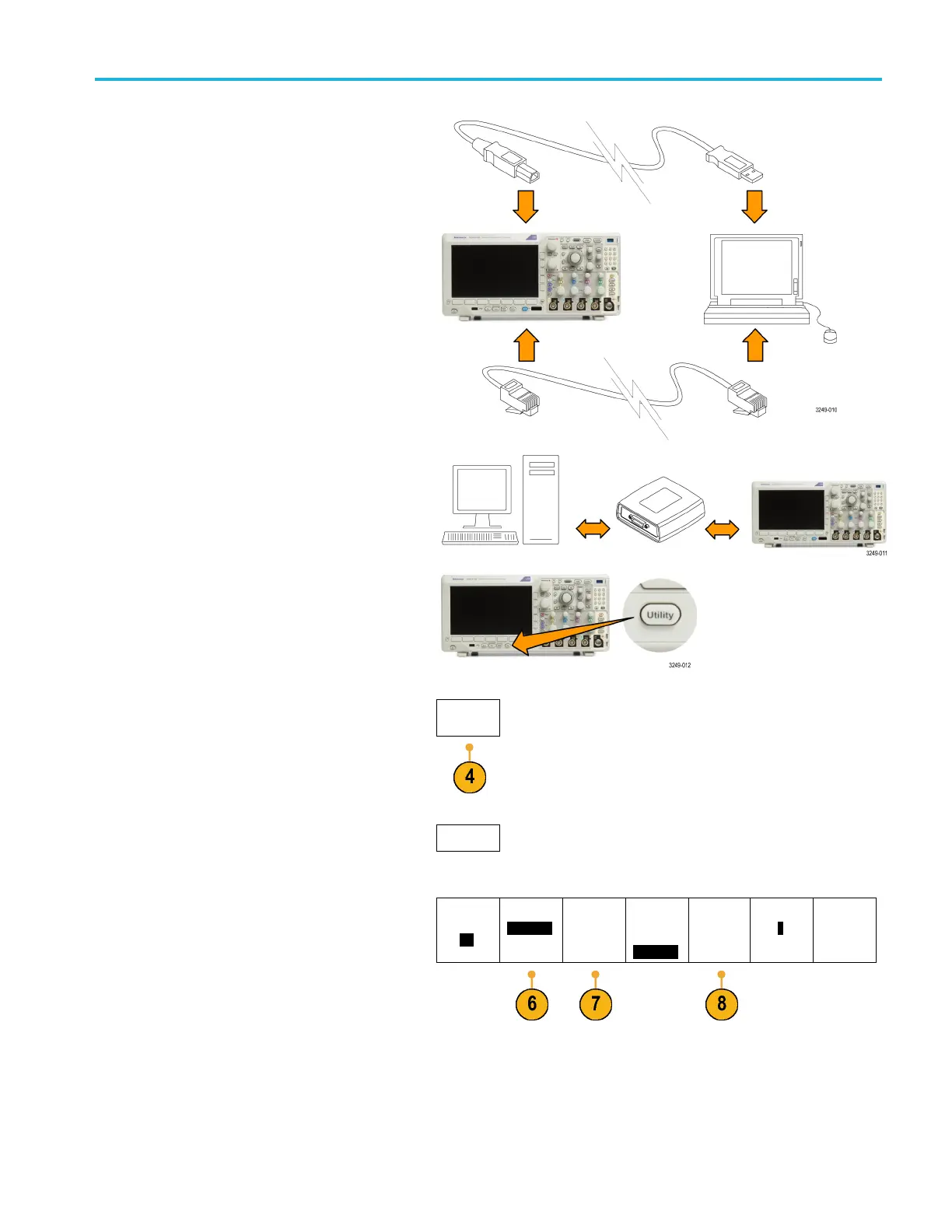
2. Connect the oscilloscope to your computer
with the appropriate USB or Ethernet cable.
To communicate between the oscilloscope
and a GPIB system, c onnect the oscilloscope
to the TEK-USB-488 GPIB-to-USB Adapter
with a USB cable. Then connect the adapter
to your GPIB system with a GPIB cable.
Cycle the power on the oscilloscope.
3. Push Utility.
4. Push Utility Page.
Utility
Page
5. Turn Multipurpose a and select I/O .
I/O
6. If you are using USB, the system sets itself
up automatically for you, if USB is enabled.
Uti
lity
Page
I/O
USB
Co
mputer
Ethernet &
LXI
Net
work
Congura-
tion
Au
tomatic
Socket
Ser
ver
GPIB
1
Check USB on the l ower menu to be sure
tha
t USB is enabled. If it is not enabled, push
USB. Then push Connect to Computer on
the side menu.
MDO3000 Series Oscilloscopes User Manual 27

Table of Contents

Other manuals for Tektronix MDO3024

Questions and Answers:

Question and Answer IconNeed help?

Do you have a question about the Tektronix MDO3024 and is the answer not in the manual?

Tektronix MDO3024 Specifications

General IconGeneral
Analog Channels4
Bandwidth200 MHz
Sample Rate2.5 GS/s
Record Length10 Mpoints
Digital Channels16 (optional)
Spectrum Analyzer Frequency Range9 kHz to 3 GHz
Digital Voltmeter4-digit
Vertical Resolution8 bits
Operating Temperature0 °C to +50 °C
Display9-inch WVGA (800x480) color display
ConnectivityUSB, LAN, GPIB (optional)
Arbitrary Function Generator50 MHz
Trigger ModesEdge, Pulse Width, Logic, Video, Runt, Rise/Fall Time, Setup/Hold
Input Impedance1 MΩ ±1%
Max Input Voltage300 VRMS
Trigger TypesEdge, Pulse Width, Logic, Video, Runt, Rise/Fall Time, Setup/Hold

Related product manuals