Input signal requirements
Keep the input signals within allowed limits to ensure the most accurate measurements and prevent damage to the analog and digital
probes or instrument.
Make sure that input signals connected to the instrument are within the following requirements.
Input Description
Analog input channels and AUX In, 1 MΩ
setting, maximum input voltage at BNC
300 V
RMS
Measurement Category II
Digital input channels, maximum input
voltage range at digital inputs
Observe probe ratings
P6316 Logic Probe
Check that the instrument passes power-on self tests
Power-on self tests verify that all instrument modules are working correctly after power up.
Procedure
1. Power on the instrument and wait until the instrument screen appears.
2. Select Utility > Self T
est from the top-edge Menu bar to open the Self Test configuration menu.
3. Check that the status of all power-on self tests are Passed.
If one or more power-on self tests shows Failed:
1. Power cycle the instrument.
2. Select Utility > Self Test. If one or more power-on self tests still shows Failed, contact Tektronix Customer Support.
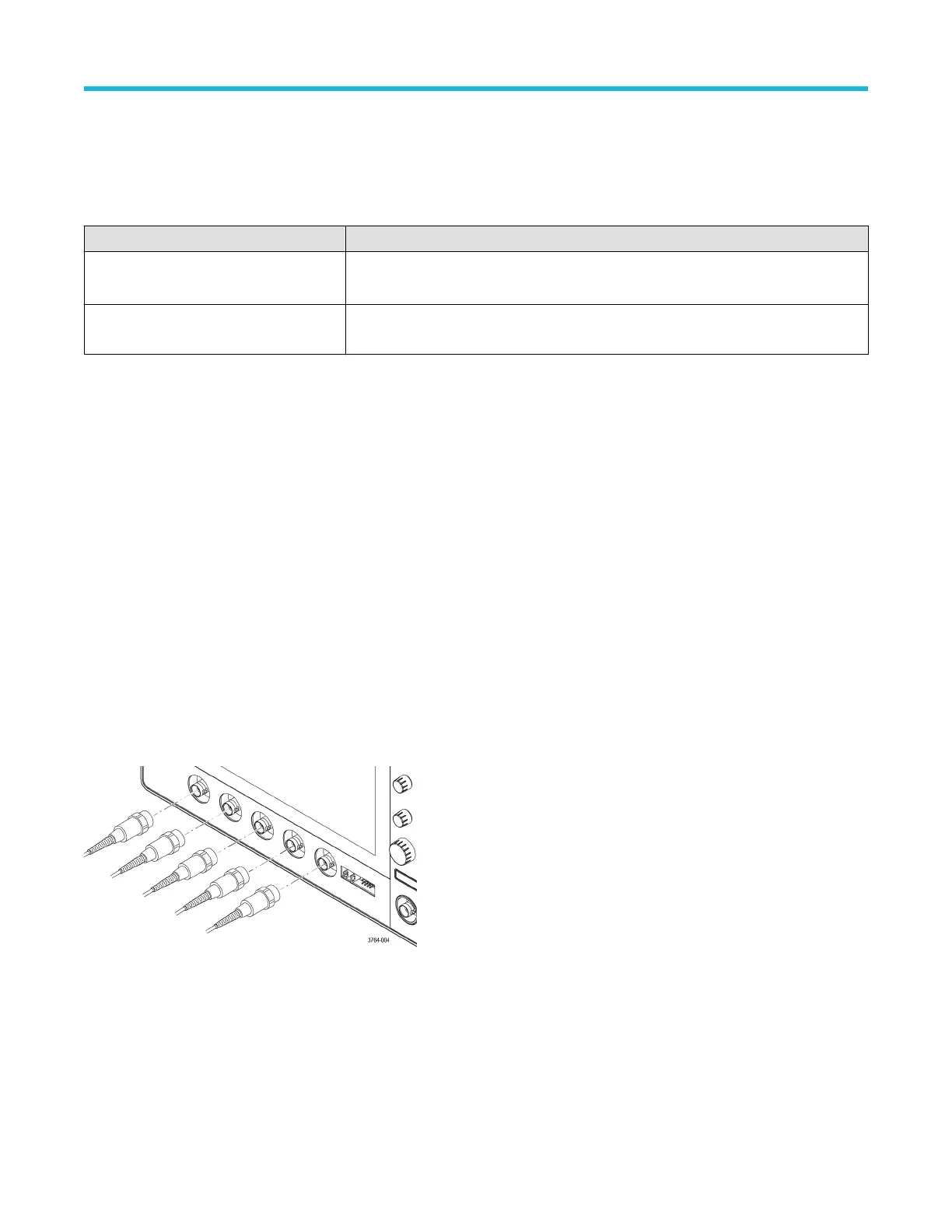
Connecting probes to the instrument
Probes connect the instrument to your device under test (DUT). Use a probe that best matches your signal measurement needs.
Connect a BNC passive probe or cable by pushing it onto a channel BNC bayonet connector and turn the lock mechanism clockwise until it
locks.
Preface
2 Series Mixed Signal Oscilloscopes MSO24, MSO22 Quick Start Manual 17