EasyManua.ls Logo

Tektronix MSO24 User Manual

Tektronix MSO24
64 pages
To Next Page IconTo Next Page
To Previous Page IconTo Previous Page
Page #28 background image
User interface elements
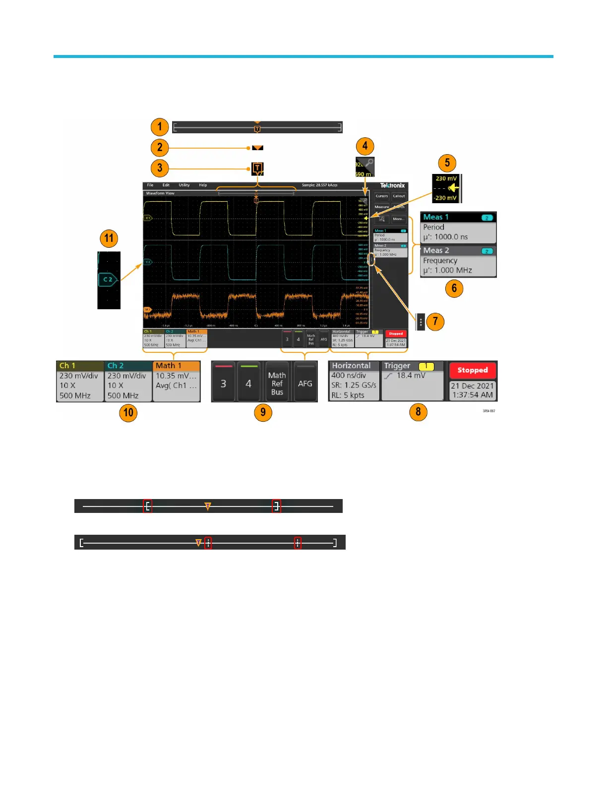
Each area of the user interface has a specific function that helps manage information or controls.
1. The Waveform Record View is a graphical high-level view of the overall waveform record length, how much of the record is on the
screen (shown in brackets), the location of key time events including the trigger event, and the current position of waveforms cursors.
If you are displaying a Reference waveform that is shorter than the current acquisition record length, or you are changing the
horizontal time scale while the oscilloscope acquisition is stopped, the brackets change position to show the part of the waveform
record that is being viewed relative to the current acquisition total record length.
If cursors are active on a waveform, the Waveform Record View shows the relative cursor positions as small vertical dashed lines.
When in Zoom mode, the Waveform Record View is replaced with the Zoom Overview.
2. The Expansion Point icon on the waveform view shows the center point around which the waveform expands and compresses when
changing horizontal settings.
3. The T
rigger Position Indicator shows where the trigger event occurred in the waveform record. The trigger icon is displayed in the
waveform slice that is the trigger source.
4. The Zoom icon switches zoom on and off. The front panel Multipurpose knobs also turn on zoom mode and change the position and
horizontal size of the Zoom Box.
5. The Trigger Level Indicator icon shows the trigger level on the trigger source waveform. Some trigger types require two trigger levels.
6. Measurement and Search badges show measurement and search results.
7. The Results Bar Handle opens or closes the results bar, to maximize waveform screen viewing when needed. To reopen the results
bar, either tap the handle icon or swipe left from the right side of the display.
Getting acquainted with your instrument
28

Table of Contents

Question and Answer IconNeed help?

Do you have a question about the Tektronix MSO24 and is the answer not in the manual?

Tektronix MSO24 Specifications

General IconGeneral
Bandwidth200 MHz
Channels4
Sample Rate1 GS/s
Display Size10.1 inch
Mixed Signal AnalysisYes
Waveform GenerationNo
Digital VoltmeterNo
ConnectivityUSB, LAN
Form FactorBenchtop
Display Resolution1280 x 800
Display ColorColor
Display TypeLCD
Trigger ModesEdge, Pulse, Logic, Video

Summary

Important safety information

General safety summary

General safety precautions to prevent injury and product damage.

To avoid fire or personal injury

Specific warnings to prevent fire and personal injury during operation.

Probes and test leads

Guidelines for safe usage of probes and test leads.

Service safety summary

Safety instructions for qualified personnel performing maintenance or service.

Terms in this manual

Definitions of WARNING and CAUTION statements.

Symbols on the product

Explanation of symbols found on the product and their meanings.

Compliance information

Safety compliance

Details on safety standards and equipment type compliance.

Pollution degree description

Describes environmental pollution degrees affecting product usage.

Measurement and overvoltage category descriptions

Explains categories for terminal ratings and safe voltage levels.

Environmental compliance

Information on environmental impact, recycling, and battery handling.

Security disclaimer

Disclaimer regarding network security and user responsibility.

Preface

MSO22 and MSO24 key features and benefits

Overview of the main features and advantages of the oscilloscopes.

Product documentation

Lists primary product-specific documentation available for download.

Install option upgrade licenses

Steps to install software option licenses for enhanced functionality.

Check shipped accessories

Instructions to verify all ordered items were received in the package.

Operating requirements

Specifies environmental, power, and altitude requirements for safe operation.

Input signal requirements

Details on allowed input signal limits to ensure accurate measurements.

Connecting probes to the instrument

Procedure for properly connecting measurement probes to the oscilloscope.

Getting acquainted with your instrument

Front panel controls and connectors

Identifies and describes front panel controls and input/output connectors.

Button and knob functions

Explains the operational function of each button and multipurpose knob.

Rear and side panel connections

Details the various connectors available on the rear and side panels.

Instrument stand installation

Instructions for mounting the instrument using the provided stand in multiple configurations.

User interface

Overview of the touch screen interface, including menus and display areas.

User interface elements

Describes the function of individual UI components like badges, views, and indicators.

Badges

Explains different types of badges and how to use them for quick access.

Configuration menus

How to use configuration menus to set instrument parameters efficiently.

Zoom user interface

Tools and methods for magnifying waveforms to view signal details.

Using the touch screen interface for common tasks

Common UI tasks and their mouse equivalents for interaction.

Configure the instrument

Download and install latest instrument firmware

Procedure to update the instrument's firmware for optimal performance and features.

Set time zone and clock format

How to configure time zone and clock display settings for accurate logging.

Run Signal Path Compensation (SPC)

Procedure to run SPC for accurate DC measurements and performance.

Compensate the probe

Steps to adjust probe compensation for optimal waveform capture and measurement accuracy.

Operating basics

Add a channel waveform to the display

How to display analog or digital channel signals on the waveform view.

Configure channel or waveform settings

Setting parameters like vertical scale, coupling, and bandwidth for channels/waveforms.

Autoset to quickly display a waveform

Automatically adjust settings to display a triggered waveform for analysis.

How to trigger on a signal

How to select and configure trigger event types and conditions.

Set the acquisition mode

Procedure to set the method the instrument uses to acquire and display signals.

Set Horizontal parameters

How to set horizontal time base parameters like scale and delay.

Add a math, reference, or bus waveform

Creating new waveforms from calculations or data for analysis.

Add a measurement

Selecting and adding various measurements to the results bar.

Configure a measurement

Refining measurement parameters and adding statistical readouts to badges.

Add a Search

Setting search criteria to find and mark specific events on waveforms.

Delete a Measurement or Search badge

Removing measurement or search badges from the results bar.

Change waveform view settings

Adjusting display modes, interpolation, persistence, and intensity.

Display and configure cursors

Adding and configuring on-screen cursors for precise measurements.

Connect the oscilloscope to a PC using a USB cable

Connecting the instrument to a PC for remote control and data transfer.

Maintenance

Inspection and cleaning

Procedures for inspecting for damage and cleaning the instrument's exterior and interior.

Exterior cleaning (other than display)

How to clean the chassis, knobs, and connectors safely.

Flat panel display cleaning

Instructions for cleaning the flat panel display screen without damage.

Check for common problems

Troubleshooting common failure symptoms and identifying possible causes.

Service the instrument

Returning the instrument for service

Related product manuals