8. The System badges show global instrument settings (Horizontal, T
rigger, Run/Stop status, and Date/Time).
9. The Inactive Channel buttons add channel waveforms to the Waveform view and add an associated Channel badge to the Settings
bar.
The optional AFG button opens the AFG configuration menu to set and enable the AFG output. This button is only present if the AFG
option is installed.
The optional PG button opens the PG configuration menu to set and enable the PG output. This button is only present if the DPG
option is installed.
The optional D15-D0 button opens the digital channel configuration menu to set and enable the digital channel. This button is only
present if the 2-MSO option is installed.
10. Double-tap a badge to open its associated configuration menu. If you add more Channel or Waveform badges than can fit in the
waveform badge display area, tap the scroll buttons at each end of the waveform badge area to scroll and display hidden badges.
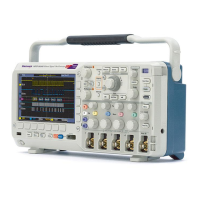
11. The Waveform Handles on each waveform identify the source of that waveform (Cx for channels, Mx for Math waveforms, Rx for
Reference waveforms, Bx for bus waveforms). The waveform handles are at the zero-volt level of the waveform by default. The
currently selected waveform handle is a solid color; unselected waveform handles are outlined.
Double-tapping a waveform handle opens the configuration menu for that waveform.
For digital channels, the waveform handle shows the channel number. Each individual digital signal is labelled D0–D15 and is with a
different color.
Double-tapping a digital waveform handle opens the digital channel configuration menu.
Dragging a digital signal handle over another handle swaps those two signals on the waveform.
Badges
Badges are rectangular icons that show waveform, measurement, and instrument settings or readouts. Badges also provide fast access to
configuration menus. The badge types are Channel, W
aveform, Measurement, Search, and System.
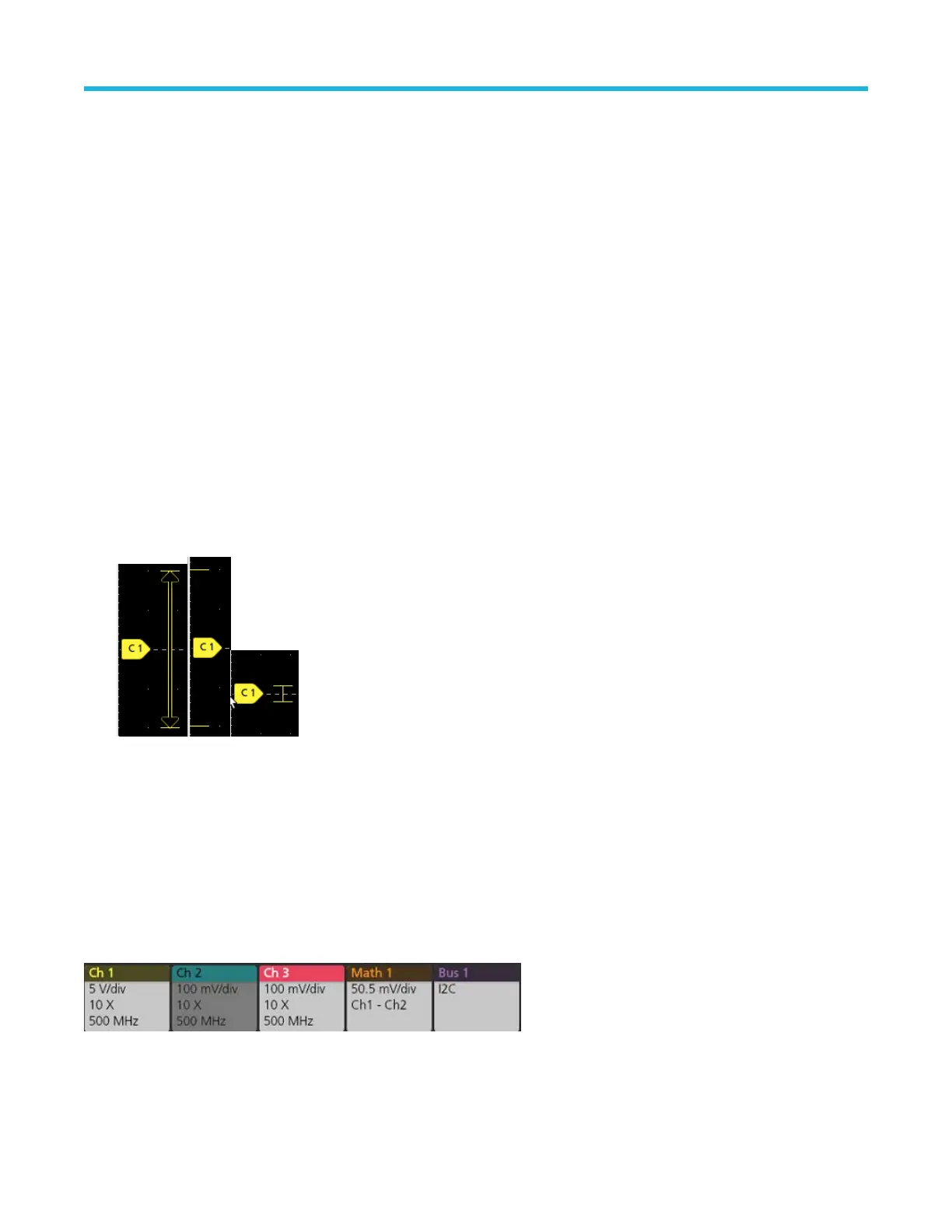
Channel and Waveform badges
Channel and Waveform (Math, Ref, Bus) badges are shown in the settings bar, located along the bottom left of the screen. Each
waveform has its own badge. The badges show high-level settings for each displayed channel or waveform. Double-tap a badge to open
its configuration menu.
Most Channel and Waveform badges also have Scale buttons, shown by single-tapping the badge. Use the Scale buttons to increase or
decrease the vertical scale setting for that waveform.
Getting acquainted with your instrument
2 Series Mixed Signal Oscilloscopes MSO24, MSO22 Quick Start Manual 29