Removal and Installation Procedures
6-22 SPG600 & SPG300 Sync Pulse Generators Service Manual
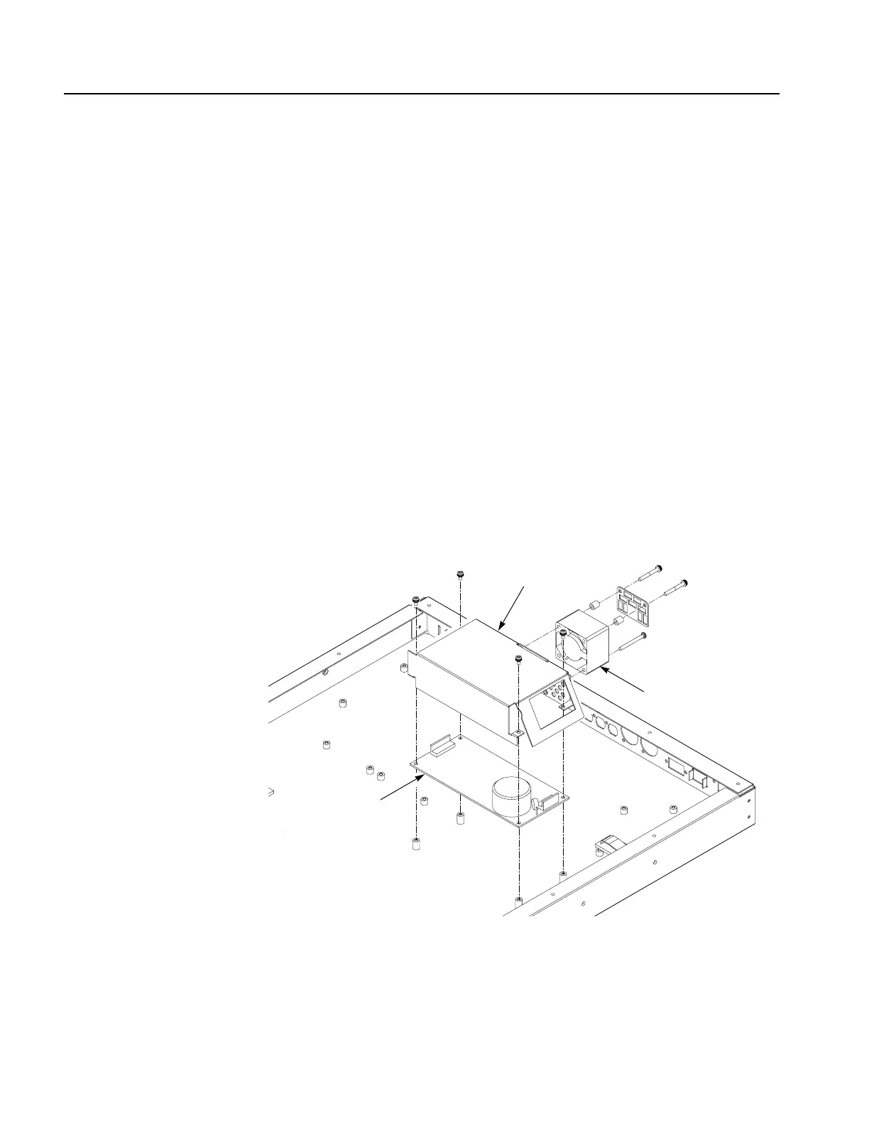
3. Remove the fan: See Figure 6-12.
a. Unplug the fan’s power cable from J5 on the A10 Main board.
b. Use a screwdriver with a #2 Phillips tip to remove the three screws
securing the fan to the power supply shield.
c. Lift the fan up and away from the shield to complete the removal.
4. Remove the power supply: See Figure 6-12.
a. Unplug the two cables from the RFI filter.
b. Unplug the cable from A10 Main board at J900.
c. Use a screwdriver with a #2 Phillips tip to remove the four screws securing
the power supply and the shield to the chassis.
d. Lift the shield up and away from the chassis.
e. Lift the power supply up and away from the chassis.
5. Reinstallation: Perform steps 3 and 4 in reverse order to reinstall the power
supply module.
Figure 6-12: Power supply module removal (SPG600)
Power supply
Fan
Shield
 Loading...


