Performance Verification
4-16 SPG600 & SPG300 Sync Pulse Generators Service Manual
11. Change the BNC cable connection from the SDI 3 connector to the SDI 4
connector.
12. Repeat step 7.
AES/EBU Digital Audio
Outputs (SPG600 Only)
This test verifies that AES/EBU digital audio signals are output correctly from the
AES 1+2, AES 3+4, AES 5+6, and AES 7+8 connectors. The following equipment
is required for this test:
Oscilloscope
Digital audio monitor
75 Ω BNC cable
75 Ω feed-through terminator
75 Ω coaxial terminator
Perform the following procedure to verify that AES/EBU digital audio signals are
output correctly from the AES 1+2, AES 3+4, AES 5+6, and AES 7+8 connectors.
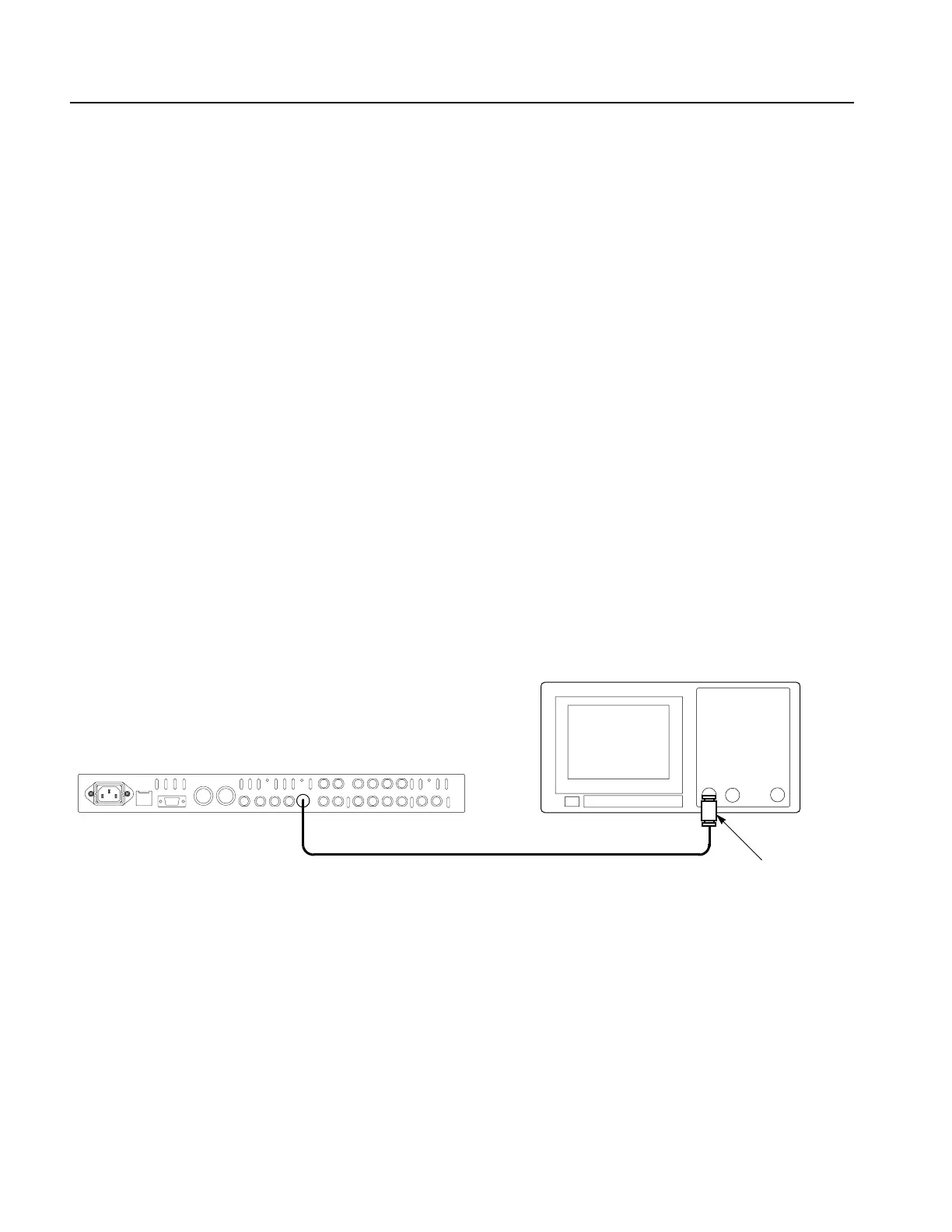
1. Use the 75
Ω BNC cable and the 75 Ω feed-through terminator to connect the
AES 1+2 connector on the sync pulse generator to the oscilloscope CH1 input.
See Figure 4-5.
Figure 4-5: Initial equipment connection for verifying the serial digital audio outputs
2. Set the oscilloscope settings as indicated below:
Vertical. . . . . . . . . . . . . . . . .200 mV/div
Horizontal . . . . . . . . . . . . . .100 ns/div
Acquire menu . . . . . . . . . . .Sample
Measure . . . . . . . . . . . . . . . .Amplitude
Trig slope. . . . . . . . . . . . . . .Rising Edge
Input impedance . . . . . . . . .1 M
Ω
SPG600 rear panel
75 Ω feed-through
terminator
75
Ω BNC cable
Oscilloscope (TDS3032B)
 Loading...


