SPG600 & SPG300 Sync Pulse Generators User Manual 3-41
Using the General Purpose Interface (GPI)
The sync pulse generator has a 9-pin, D-type connector that can be used as a
General Purpose Interface (GPI). When using the GPI connector, you can recall
one of the seven presets, output an alarm signal, and display an alarm status on the
display.
GPI Connector Pin Assignments
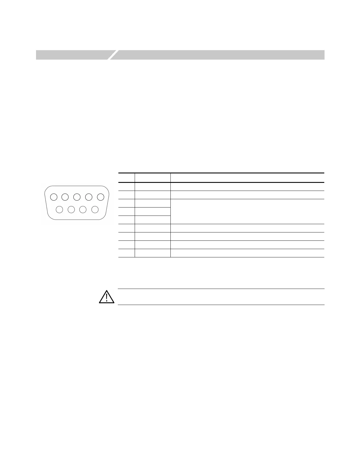
Figure 3-25 shows the pin assignments of the GPI connector. Pin 1 is used to output
an alarm signal. Pins 3, 4, and 5 are used to input signals for recalling a preset.
Figure 3-25: Pin assignments of the GPI Connector
Pin Description Notes
1 Output Low
< 0.4 V or ground (when drawn 100 mA; maximum 4 Ω)
2 Unused ----------
3 Input
High
> 1.4 V or open (connected to an internal 10 kΩ pull-up resister)
Low
< 0.4 V or ground (input impedance: 10 kΩ)
4 Input
5 Input
6 Ground ----------
7 Reserved ----------
8 Reserved ----------
9 Ground ----------
12345
9876
GPI connector
CAUTION. Do not connect any wires to pin 7 and 8. Doing so can result in damage
to the instrument.
 Loading...


