Operating Basics
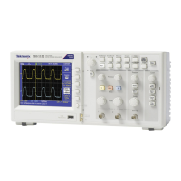
Input Connect
ors
1&2. Input connectors for waveform display.
Ext Trig. Input connector for an external trigger source. Use the Trigger Menu to
select the
Ext, or Ext/5 trigger source. Push and hold the Trig View button to see
how the trigger settings affect the trigger signal, such as trigger coupling.
Other Front-Panel Items
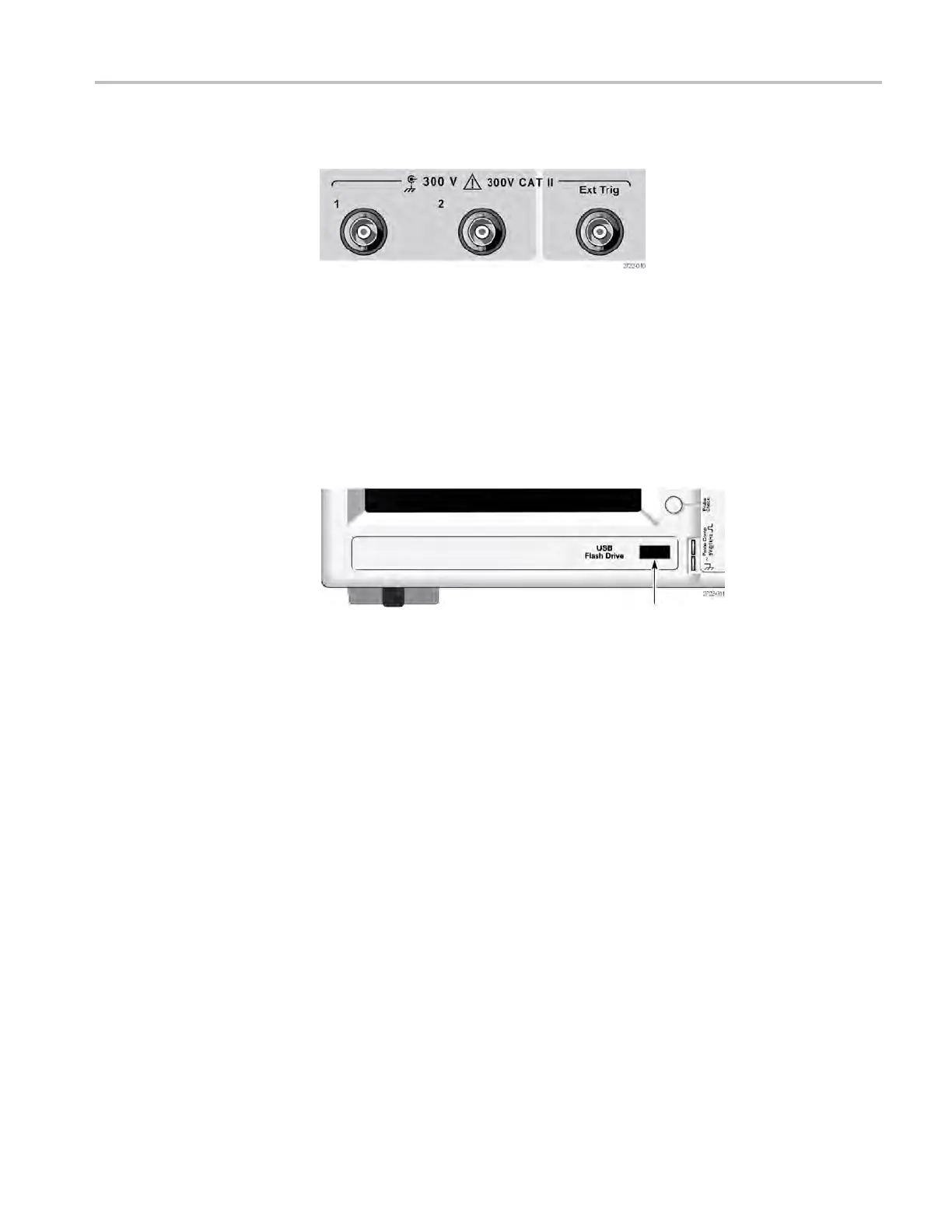
USB Flash Drive p ort
USB Flash Drive Port. Insert a USB flash drive for data storage or retrieval. The
oscilloscope displays a clock symbol to indicate when the flash drive is active.
After a file is saved or retrieved, the oscilloscope removes the clock, and displays
a hint line to notify you that the save or recall operation is complete.
For flash drives with an LED, the LED blinks when saving data to or retrieving
data from t he drive. Wait until the LED stops to remove the drive.
PROBE COMP. Probe compensation output and chass is reference. Use t o
electrically match a voltage probe to the oscilloscope input circuit.(See page 11,
Manual Probe Compensation.)
TBS1000 Series Oscilloscopes Installation and Safety Manual 23
 Loading...