Performance Ver
ification
Gain Accuracy
WARNING. Dang
erous voltages will be present on the calibration generator output terminals and connection cables. Always
verify that the generator is in the standby mode before you make any connections to the generator.
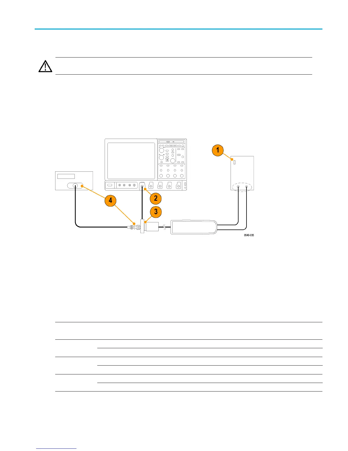
1. Verify that the generator output is off.
2. Connect the probe calibration fixture to any channel (1–4) on the oscilloscope.
3. Connect the probe output to the probe calibration fixture and the probe inputs to the generator.
4. Connect the output of the probe calibration fixture to the inputs of the DMM, using coax cables and adapters. Set the
DMM to AC volts.
5. Set the probe attenuation to the lower range for the probe that you are testing. (See Table 11.)
6. Set the generator square wave output frequency and RMS voltage (main display) to the values shown in the table
for the probe that you are testing.
7. Enable the generator output and record the probe output (as displayed on the DMM) in the test record.
8. Disable the generator output.
9. Set the probe attenuation to the next range and then repeat steps 6 through 8.
Table 11: Gain accuracy equipment settings
Probe Generator output Probe output voltage
Model Range Voltage (rms) Frequency Expected (rms) Measured (rms)
600 V 75 V 100 Hz 750 mV ±15 mVTHDP0100
6000 V 75 V 100 Hz 75 mV ±15 mV
150 V 25 V 100 Hz 500 mV ±10 mVTHDP0200
1500 V 75 V 100 Hz 150 mV ±3 mV
75 V 20 V 100 Hz 800 mV ±16 mVTMDP0200
750 V 60 V 100 Hz 240 mV ±4.8 mV
THDP0100/0200 & TMDP 0200 High Voltage Differential P robes Instruction Manual 36