Probe Operating
Information
Probe Controls and Indicators
The probes have several features that make probing and measurement a simpler task. Familiarize yourself with the controls
and indicators shown on the following pages. Some features differ from those illustrated, such as probe input voltage
limit and voltage range, depending on the probe model.
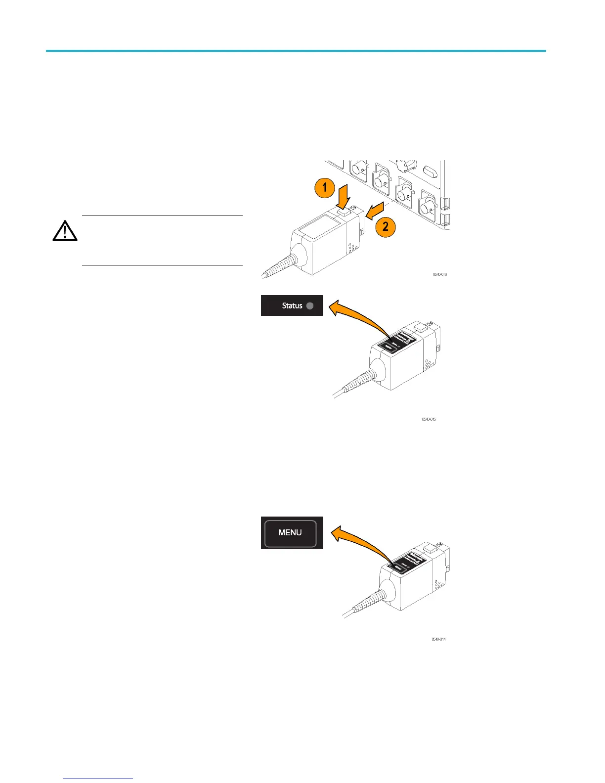
The probe release button, Status LED, and MENU buttons are located on the probe control box.
Probe Release Button
Press the release button to unlatch the probe
from the instrument, and then pull the probe
straight ou
t.
WARNING. To avoid electrical shock,
disconnect the probe inputs from the circuit
before dis
connecting the p robe from the
instrument.
Status LED
When the probe is connected to the
instrument, the Status LED lights amber as
the probe completes a self-test. Then, the
Status LED goes off briefly and then lights
green to indicate the probe is ready to use.
The Status LED lights amber or red i f the
power-on test failed, or any time an error
occurs. If the Status LED l ight does not light
green after the self-test, first disconnect the
probe from the circuit under test, and then
disconnect the probe from the oscilloscope.
Reconnect the probe to the oscilloscope and
check that the Status LED lights amber, and
then green. If the Status LED continues
to light amber or red, there may be other
remedies. (See page 53, Error Conditions .)
Menu Button
Press the ME NU button to display on-screen
probe controls on the oscilloscope. Many
pro
be functions are available, such as
AutoZero and range selection.
3 THDP0100/0200 & TMDP0200 High Voltage Differential Probes Instruction Manual