Probe Operating
Information
The remaining controls and features of the probe are located on the probe head.
Probe Inputs
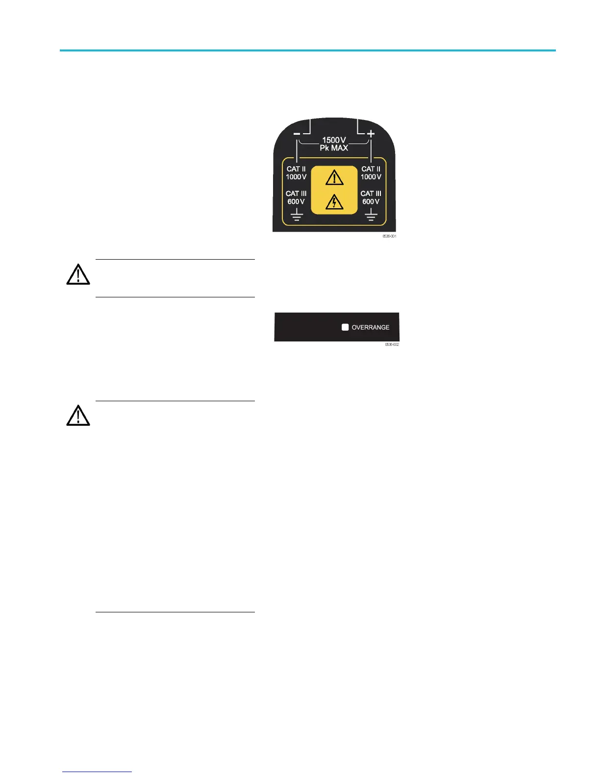
The maximum voltage that the probe inputs
can accept depend on the probe model and
the measurement points.
For example, the THDP0200 probe (shown)
can measure a maximum of 1,000 V
RMS
CAT
II between either input and ground, and a
maximum difference of 1,500 V (DC + peak
AC) between the (–) and (+) inputs. These
input ratings are valid for both range settings.
The other probes covered in this manual
have different limits; refer to Specifications.
(See Table 6 on page 27.)
CAUTION. Do not use these probes above
the input limits shown on the probes. The
input voltage limits vary by probe model.
Overrange Indic ator
The OVERRANGE indicator lights r ed if
the voltage of the input differential signal
exceeds
the linear range of the range setting.
When this happens, the signal on the probe
output does not accurately represent the
signal
on the probe input.
WARNING. The Overrange indicator
does not detect overrange condition of
commo
n-mode voltages or voltage-to-earth
potential at the probe inputs. The Overrange
indicator only detects differentially between
the + a
nd – i nputs (not relative to ground).
Do no
t exceed the common-mode voltage
or input voltage-to-earth ratings of the probe
when taking measurements. (See page 25,
Over
range Detection.)
If yo
u are not sure, make a single-ended
measurement of each point you are intending
to measure differentially first. Make a
sin
gle-ended measurement by tying one
input lead to ground (the "–" input) and then
connecting the other lead (the “+" input) to
the
points of interest, one at a time.
THDP0100/0200 & TMDP 0200 High Voltage Differential P robes Instruction Manual 4