Probe Operating
Information
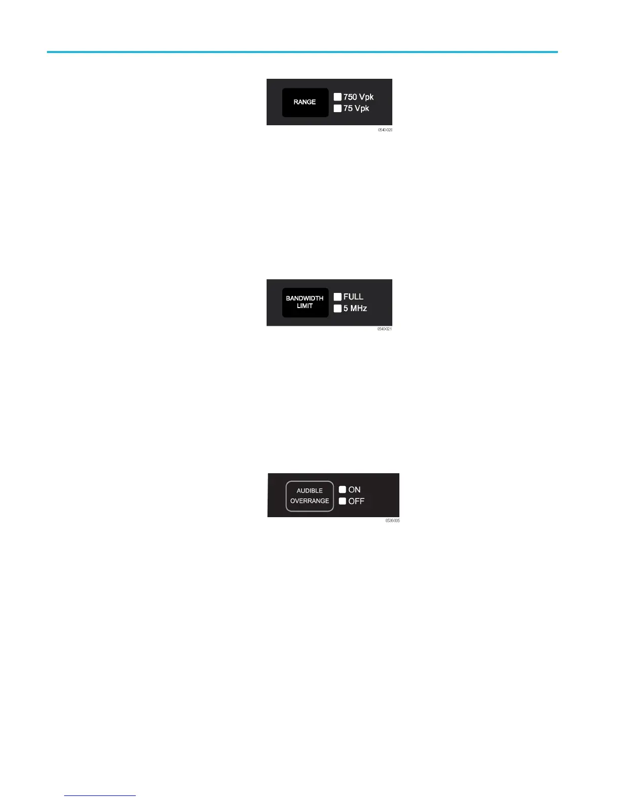
Voltage R ange Button and
Indicators
Press the RANGE button to select between
the v oltage range (attenuation) settings of
the probe. The voltage range is indicated by
two LE Ds on the probe and may be displayed
on the oscilloscope screen, depending on
the oscilloscope model.
The OVERRANGE LED lights if the applied
voltage exceeds the selected range. To
extinguish the LED, select a higher range.
If a higher range is not available, do not
attempt to take the measurement with the
probe.
Bandwidth Limit Button and
Indicators
Press the BA NDWIDTH LIMIT button to
limit the probe bandwidth to 5 M Hz. 5 MHz
is close t
o the switching frequency of m ost
switching transistors (FETs) in switch mode
power supplies (SMP S).
The 5 MHz
filter assists in the characterization
and testing of power supplies in switch mode
by removing all high frequency content, noise
and har
monics from the measurement.
Press the button again to return to the FULL
position, which selects the full specified
bandwi
dth of the probe.
Audib
le Overrange On/Off Button
and Indicators
The audible overrange is an audible alarm
that indicates when the m easured signal
exceeds the selected range. The alarm is
enabled when the probe is first powered on.
Press the AUDIBLE OVE RRANGE button to
light the OFF LED and disable the feature.
To enable the alarm, press the button again
to light the ON LED.
5 THDP0100/0200 & TMDP0200 High Voltage Differential Probes Instruction Manual