Adjustment Procedures
5-6
TLA5000 Series Service Manual
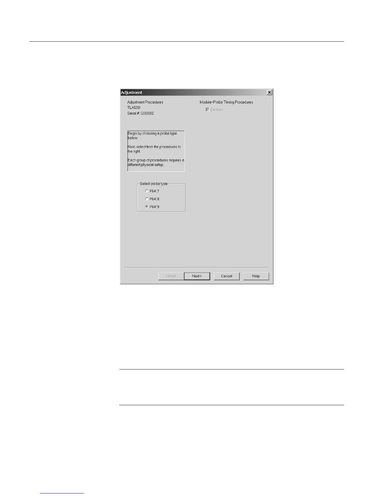
4. Verify that Deskew is selected under the Module+Probe Timing Procedures.
Figure 5- 3: Default Adjustment procedure dialog box
5. Click the Next button at the bottom of the dialog box to display the probe
connection instructions. Follow the on-screen instructions to connect the
probes from the logic analyzer to the test fixture. If necessary, refer
Figure 5--4 on page 5--7 and to the test fixture label to determine the correct
probe connection.
NOTE. When connecting the P6419 Logic Analyzer probes, make sure that the
alignment pin on the probe head aligns with the hole on the test fixture. Tighten
the probe head screws by alternating between them until they are finger tight (no
more than 1 in-lbs of torque).
6. Click the Next button to begin the procedures.
The software will begin the adjustment procedures and display the results of
the first 34 channels in the window.
 Loading...


