Removal and Installation Procedures
6-10
TLA5000 Series Service Manual
Right-Side Cover
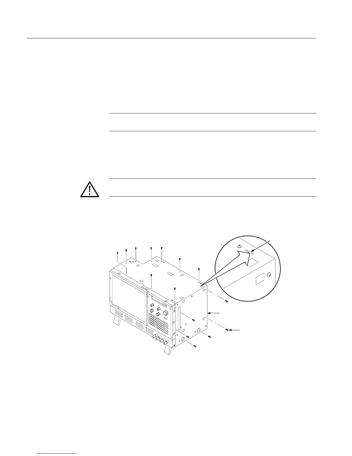
Remove the right-side cover to access most of the internal components of the
instrument. Refer to Figure 6--2 while removing the right-side cover.
1. Remove the top and right trim to access the right-side cover.
NOTE. All mounting screw holes are indicated by a star etched around the
mounting hole.
2. Remove the 15 T-15 Torx-drive screws that secure the cover to the top and
right sides of the chassis.
3. Remove the cover.
CAUTION. Take care not to bind or snag the covers on the internal cabling as you
remove or install.
4. To reinstall the right-side cover reverse steps 1 through 3. Tighten the T-15
Torx-drive screws to 8-in lbs.
T-15 Torx-drive
screws (14)
Right side cover
Tab
Figure 6- 2: Right-side cover removal

 Loading...


