3
M1
M2
1
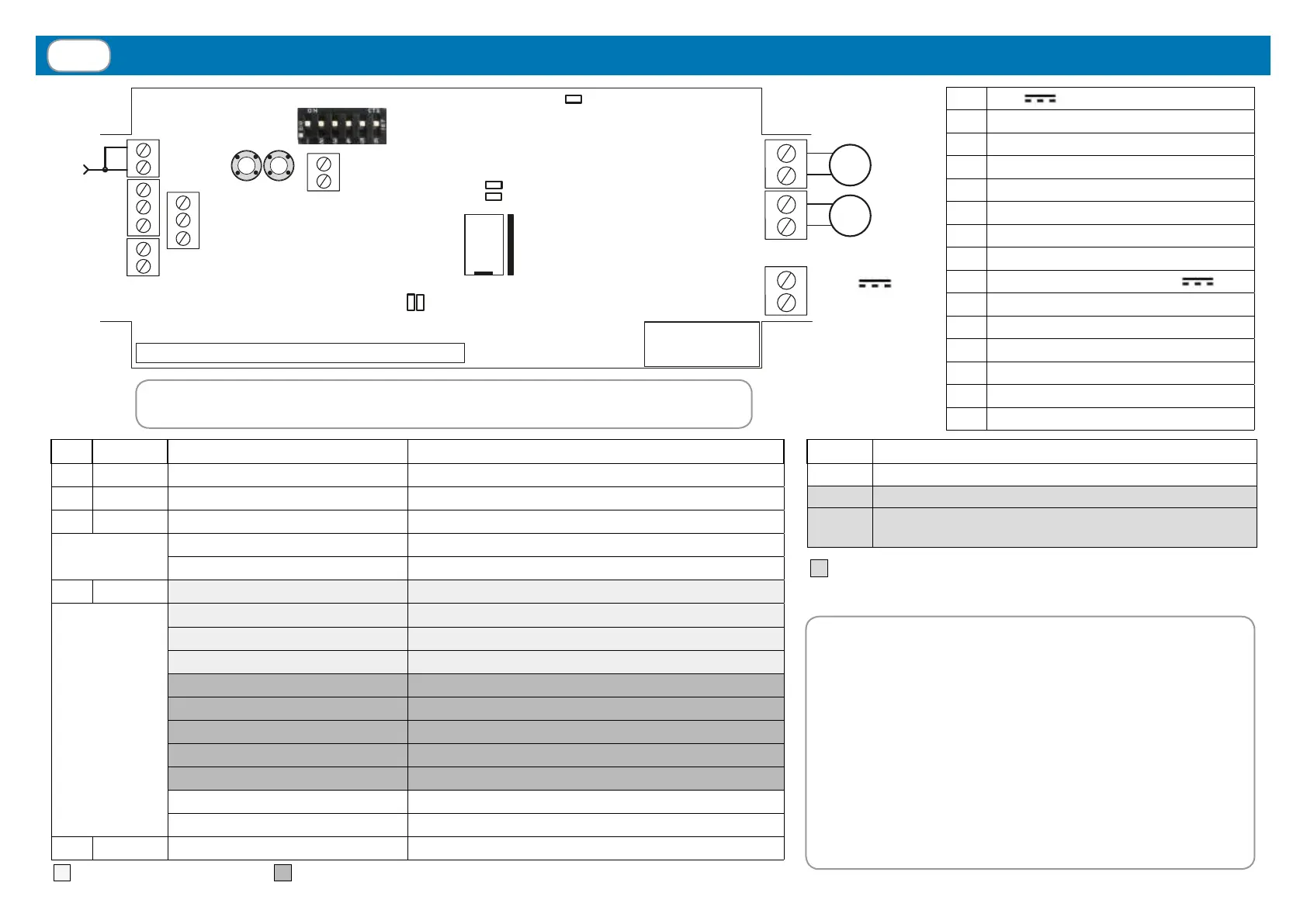
Connections, adjustments and control unit warnings
1
+24V
POWER SUPPLY
2 POWER SUPPLY GND
3 MOTOR 1 (OPEN)
4 MOTOR 1 (CLOSE)
5 MOTOR 2 (OPEN)
6 MOTOR 2 (CLOSE)
7 WIND SENSOR (BROWN)
8 WIND SENSOR (BLUE)
9
RAIN SENSOR (WHITE, +12V
)
10 RAIN SENSOR (BLUE, SIGNAL)
11 RAIN SENSOR (YELLOW, GND)
12 AERIAL RF
13 AERIAL GND
14 TEMPERATURE SENSOR (BLACK)
15 TEMPERATURE SENSOR (WHITE)
LED COLOUR STATUS MEANING
L1 RED ON until next manoeuvre MOTOR 1: Limit switch or alarm
L2 RED ON until next manoeuvre MOTOR 2: Limit switch or alarm
L3 BLUE ON Synchronized mode activated
One ash every second Synchronized mode activated (during conguration)
One ash every 2 s Independent mode activated (during conguration)
L4 RED One ash every 10 s Water draining alarm (par. 4.4)
Two quick ashes every 10 s Rain alarm (par. 4.4)
Three quick ashes every 10 s Ice / Snow alarm (par. 4.2 - 4.3)
Four quick ashes every 10 s Wind alarm (par. 4.1)
Five quick ashes Unexpected absorption of one motor in synchronized mode
Six quick ashes Built-in motor limit switch activated
Seven quick ashes Motor stopped by current absorption over the threshold
Eight quick ashes Safety limit switch
Ten quick ashes One motor is short-circuited
One ash every 2 s Rain sensor is deactivated
One ash every 3 s Temperature sensor is deactivated
L5 RED ON Power ON
Optional LED CARD
(only in TVPLA868CC2(S) version)
Memory
10A Fuse
24V
Power supply
-
+
RAIN
sensor
WIND
sensor
Aerial
TEMP.
Sensor
ATTENTION! The electronic board is protected by a 10A fuse.
The maximum allowed power, including the plug-in LED controller board, is 240W.
= Weather sensor alarms = MOTOR alarms
FIRST POWER ON: at rst power-on, the system is
waiting to be programmed with the memorization of
at least one transmitter (par. 3) and the conguration
of the motors and relative working time (see below).
MOTOR CONFIGURATION: Identify the correct
product application from the 3 given below and follow
the relative conguration procedure. Attention: if
the wrong application is selected, the conguration
procedure must be repeated for the correct application.
= It takes effect DURING conguration
DIP MEANING
1 - 2 - 3 Setting of wind sensor threshold (see par. 4.1)
4 - 5 Motor control mode (see pages 4…7)
6
Maximum motor current threshold set during conguration
(see par. 2.4)
2
1
6
5
4
3
14
15
13
12
P1 P2
L5
DIP switch
8
7
11
10
9
L3
L2
L1
L4
Not
used