User Manual
7
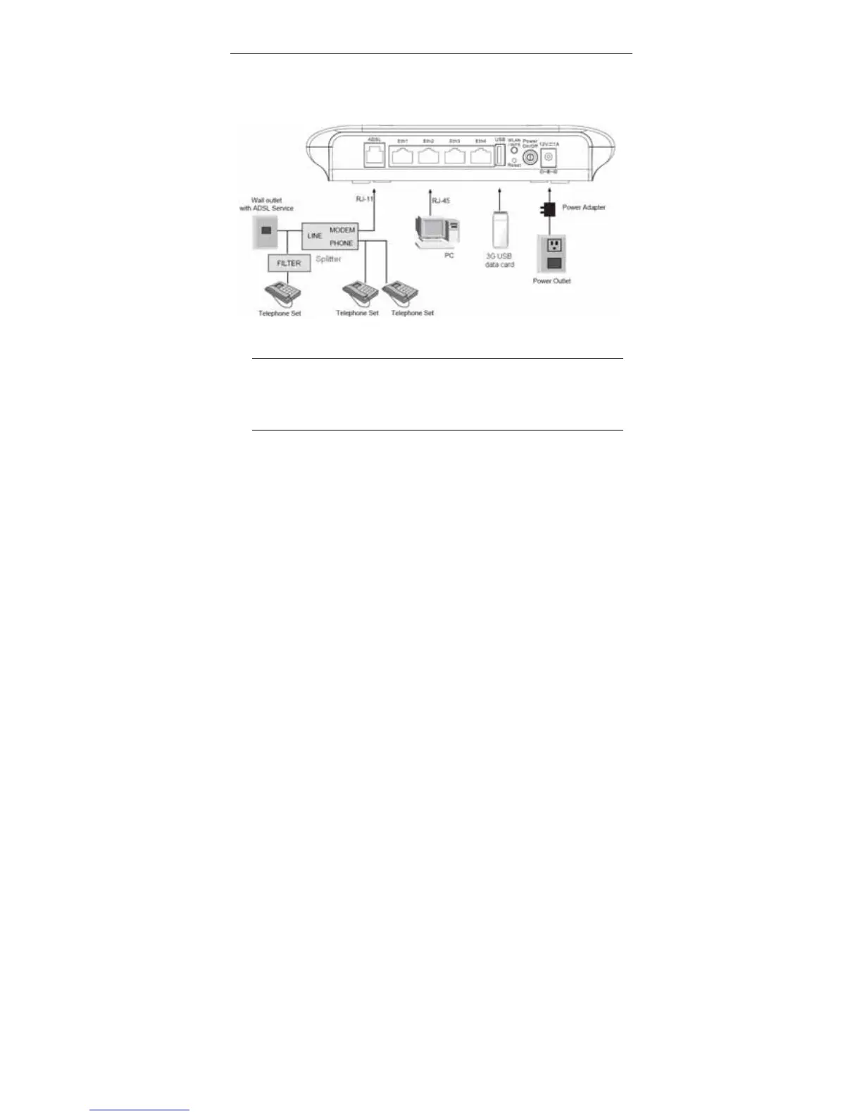
Connection 2: Figure 4 displays the application diagram for the connection of
the device, PC, splitter and telephone sets when a telephone set is placed before
the splitter.
As illustrated in the following figure, the splitter is installed close to the device.
Figure 4 Connection diagram (with a telephone set before the splitter)
Note:
When connection 2 is used, the filter must be installed close to the
telephone cable. See Figure 4. Do not use the splitter to replace the
filter.
Installing a telephone directly before the splitter may lead to failure of connection
between the device and the central office, or failure of Internet access, or slow
connection speed. If you really need to add a telephone set before the splitter,
you must add a microfilter before a telephone set. Do not connect several
telephones before the splitter or connect several telephones with the microfilter.