Controls and Operating
3-21
'0' - Power switched off. All electrical systems are inoperative.
NOTICE: Hazard warning light illumination is possible when the switch is
in 0.
'1' - Power switched on, instruments, gauges and warning lights register
as appropriate. All electrical systems are operative. The key must remain
in this position whilst operating the machine.
NOTICE: At this point the ‘Display Screen’ starts up. Sequentially all the
indicators are ON and the instruments will touch the maximum indicative
value before returning to the minimum.
Press the Start / Stop switch to start the engine. On pressing the switch
again the engine will stop.
After a few seconds, the buzzer alarm sounds to indicate that the power is
still ON.
On switching the key from 1 to 0 the power goes off. The engine will go to
low idle and after 3 seconds the engine will stop.
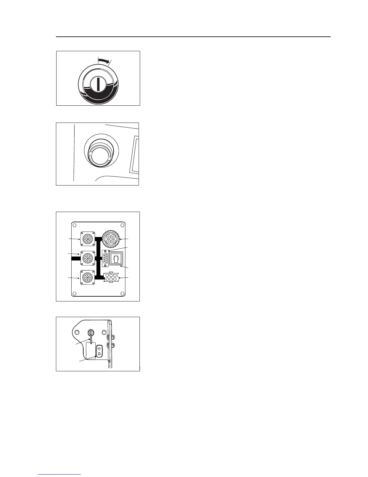
18.Diagnostic Test Point - Test points are located at the right hand side
of the cabin. This comprises a 4 plug-in connector for:
1) X36 CAN-4 : Diagnostic Bus - For special Diagnostic Equipment
2) X35 CAN-3 : HMI Bus - Dash Board, Steering Lever switch
3) X14 CAN-2 : Power Train Bus - ECU, TCU
4) X44 : For Engine Diagnostics
5) X34 : Serial Interface - MCU programming connector (RS232)
6) S25 : For manually activating specific circuits in case of emergency
7) B24 : Connector for AEB kit
19.Battery Master Switch - (Located at the left hand side of the truck in
the battery box). Turn the key clockwise to connect the batteries to the
electrical circuits. Switch the key off and remove it when leaving the
machine unattended.
20.Hood Lift Switch - Controls lifting or lowering of the hood.