Harmony Series 2 Homelift - XH00200 Issue: D Page 28 of 106
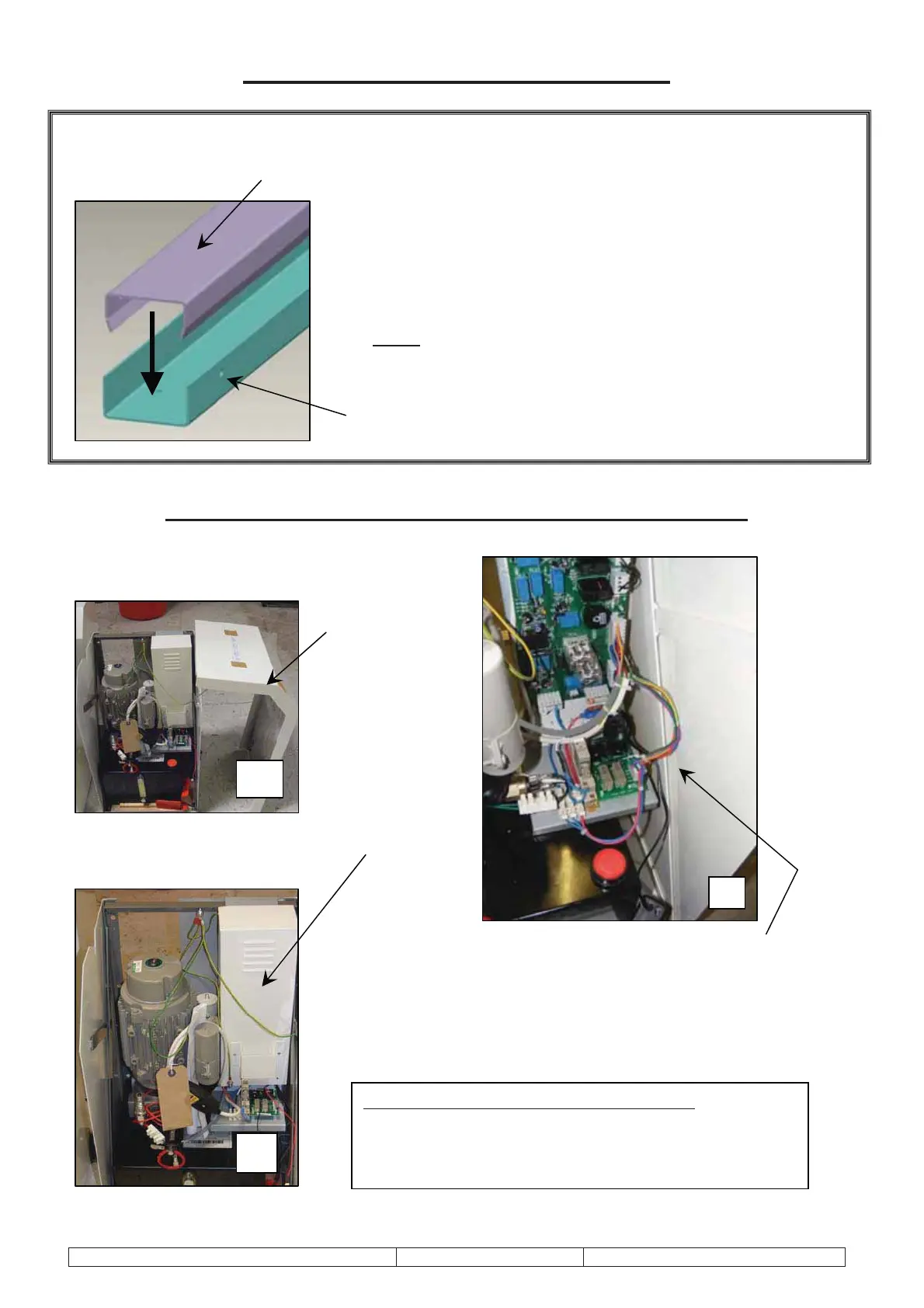
Upper Control Tube/Tray Installation
Trailing Cable Installation – at the Powerpack end
Fit upper tray (LHG2022) and control tube (LHG2032).
x Upper tray should fit into remaining gap between
middle tube/tray and upper ceiling.
x Length may need to be cut where floor to ceiling
height is less than 3090mm at upper level.
*Note:
If ceiling cap is to be fitted, cut tube 50mm
lower than upper ceiling.
Upper ‘TUBE’, slots into tray
Upper ‘TRAY’ – use pilot holes in side of tray to drill 3mm holes in tube.
Fix with 1/8” x ¼” rivets (CF472), as it will never need to be removed.
For full wiring details, see ‘Wiring Diagram 1’ within the circuit diagram section of this manual.
Trailing Cables – 2 sets of 7 core cables
x TC1 White & TC2 Grey
x One set of ends pre-wired to attach to CE966
board in powerpack
2
Slide off
internal cover
that protects
CE966 board.
1
Remove
external
cover
3
x Feed cables in from rear of powerpack. Plug
them and their associated wiring into CE966
board as shown.
x Re-attach internal cover.
x Re-attach front cover LED cable.
x Re-attach external cover.


 To Next Page